Dimension across a break in a SOLIDWORKS drawing
Sometimes the scale that makes a view fit on the paper makes
it too small to see important details on the view. In this case, using a break is a great
idea. SolidWorks allows you to choose
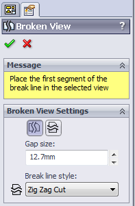
where to break the part, what kind of break line to use, as well as how large
of a gap to leave in between the two resulting sections.
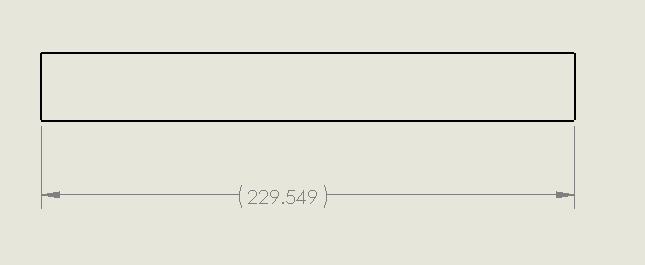
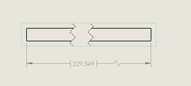
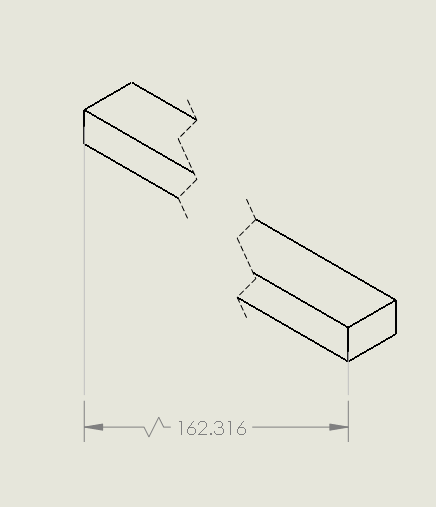
Adding a dimension works just as usual and gives the actual
dimension of the part, not as the part appears as you can see below.
Notice SolidWorks gives you that little ‘squiggle’ in the
dim. line to show you that the dimension includes the section that has been
broken, regardless of the distance set in between. Also notice that SOLIDWORKS aligns the two
sections after the break. This creates a
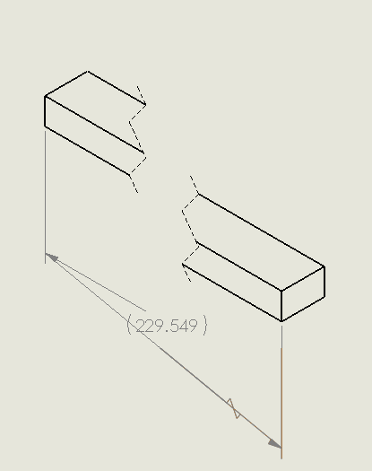
problem when it comes to Iso views and other views that are angled. Dimension these views gives you the proper
dimension of course, just aligns the dimension to the edge, therefore making it
angled as well.
You still get the ‘squiggle’ to show that the dimension includes
the break, but if for whatever reason you are looking for the dimension at that
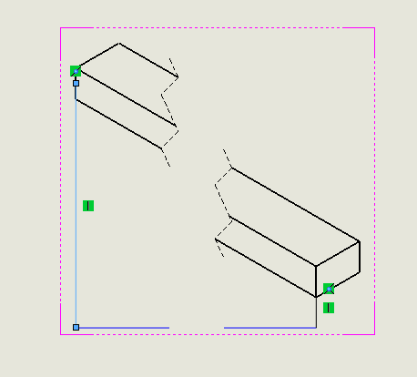
angle as opposed to the true dimension, you might be in a bind here. One possible workaround is to create a sketch
with three lines, running down from one edge, across the part then connecting
to the other edge in the following manner
Then just dimension the horizontal line, and you can hide the
unwanted part of the sketch by making it the same color as the drawing sheet. A bit of a backwards process, but it gets the
job done should you need it.
Brian Adika,
Computer Aided Technolog, Inc.

 Blog
Blog 