Submodeling in Simulation 2013
Was it really last year that Vik wrote about Two Neat Additions to Simulation in 2013? How time flies! For all its power, the addition of Submodeling studies for Simulation 2013 has seemingly gone unnoticed by our Simulation user base.
In most cases, we are usually interested in the performance of a small portion of the model, maybe a part or two of the whole design. In order to get to that area of interest, we need to analyze a load path through other components. What submodeling does is allow us to generate analysis results on an entire assembly, then utilize those results on our area of interest in the mechanism. This is done by using the displacements from the assembly and transferring those as a fixture (a prescribed displacement) on the components of interest. Let’s show how this works in Simulation.
Here is the Frame model we demonstrated Submodeling on during the SOLIDWORKS 2013 Roll-Out sessions. The boundary conditions have been applied to the entire model, but our real area of interest is the middle cross brace and associated components.

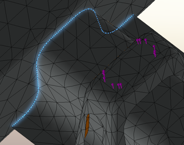
We conduct the analysis on the entire frame, specifically looking for the displacements results of the assembly. The displacements at the cut boundary between the entire frame and our important component(s) is what we are interested in to begin a submodeling study.
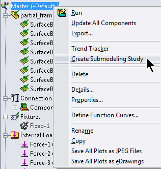
To start the Submodeling study, right-click on the Simulation study name and select the option ‘Create Submodeling Study’.
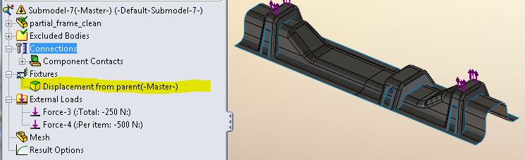
The next step is to select components – the ones we are most interested in – from the graphics window. Simulation will take a few moments to generate the derived configuration and transfer the displacement results at the cut boundary into the submodel study.
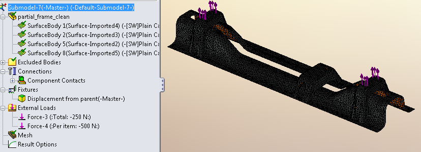
Now you can run an analysis with a very refined mesh on the important components of the design. The real benefit of submodeling in Simulation, however, has to do with evaluating design changes. If the cut boundary remains unchanged and the loading conditions stay the same, you can evaluate design changes to the submodel and verify the effectiveness of those changes without meshing and running the analysis on the entire assembly.
Here we see that a slot has been cut through the main portion of the cross frame that would remove a lot of mass from the component. We can recalculate the results of the submodel study with this design change and feel comfortable that our results are valid.
So the next time you begin a study on a large assembly, resist the temptation to drag the mesh density slider all the way to fine. Just generate results for the entire assembly with a coarse mesh, create a submodel study and then refine your mesh as you see fit. Now go make your products better with SOLIDWORKS Simulation!