How to Configure SOLIDWORKS Toolbox and Hole Wizard - Part 2
Welcome to Part2 of the SOLIDWORKS Toolbox configuration blog series. In this blog we will talk about Step2 Customize you hardware, which allows you to configure and customize your fasteners.
**As always please be sure to back-up your original Toolbox folder prior to making any changes. To be sure you have a good copy make sure to take the whole SOLIDWORKS Data folder. The default location is C:SOLIDWORKS Data. If you are not sure where your Toolbox is located go to Tools, Options, System Options tab, HoleWizard/Toolbox location.
OK enough about that… Open your Toolbox configurator and select Step 2.
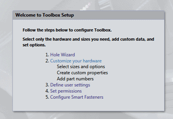
First off I would like to say there is a HUGE amount of information in this one section. The first page lists all of the standards, if you don't use some of them I would suggest that you uncheck them to help reduce the size and help users select the correct groups.
**If you are installation savvy you may have already removed the un-needed Toolbox standards during installation process. If you did not catch this in the installation process this time now you know how to catch it next time around J
We can expand each Standard on the left side of the configurator.

Each group can be modified the same way as the Standards to remove individual fastener types that are not needed.
Even further reductions in available fasteners can be made inside each type to remove Drive Types, Sizes, and Thread visibility. As you can see in this example there are nearly 33,000 possible configurations of this fastener. The number of possible configurations doesn't mean these will all be in the part. Although you could force it to generate them all (not recommended) they are not created by default. Each configuration is created in the part when it has been chosen to insert into an assembly.

Why are there so many configurations??? Let's open up the Socket Head Cap Screw click on sizes, there is a good list here. Each of the sizes can be removed by the check boxes (1) and you can add sizes using the plus symbol (2).

Let's look at the add size menu. You will need to fill out ALL of the fields to make the fastener size available. The same box selections can be made for each of the Length, Threads and so on.

You also have the choice of removing Drive Types as seen here.

Here is a look at the thread display. NOTHING in the Toolbox will make a bigger impact on the size of your fasteners and assembly performance than this area. It is best to use only the Simplified option here.
**The schematic should never be used as it increases file size and graphics load on the assembly in a big way. If you don't change any of the other options in the Toolbox that restrict users from picking fasteners at the very least explain that they should not use ANY schematic display options.

Go back to the General properties, and pick the Custom Properties button.

This box allows you to setup custom properties. There are already fields for Part Number, Description and Comment. So this is only needed for other things you may want to add. Let's set one up, Type Material in the Property name box. Also check the box for "Each value for this property requires a new configuration name", this adds another whole copy of the configurations per property item setup in here. So let's say you want to add 2 materials, Zinc Plated and Stainless Steel.

Click the List button. You can add a link to the SW material here if you wish. Otherwise just continue by selecting the Value box, and give it a Suffix.

It should look something like this when you are done.

When we click OK the configuration list will update you will then notice a custom property listed. This property is for the entire toolbox and can be checked into any fastener. Take a look at the configurations here and see the last character right now is either N, C, or S. These are from the display type N=None or Simplified, C=Cosmetic, S=Schematic.

Look what happens when we add the check for material you can set one material to default. Go up a level using the file folder icon and click back on the Socket Head Cap Screw fastener to refresh the configuration list.

Go up a level using the file folder icon and click back on the Socket Head Cap Screw fastener to refresh the configuration list. After refreshing you will see the N, C, and S are all now accompanied by a ZP or SS.

The configurations can be modified via Excel spread sheet as well by clicking this button. Use the Export Data to send it to Excel and then import it when you are done. The create configurations button is here as well but like I stated before I would probably not use that. If you have lots of extra network space and time on your hands, this will definitely take both of those from you. J

Here is an example of the Excel spreadsheet.

Lastly if you would like to copy or delete a part or group of parts you can right click them in the configurator. Once you have copied a part you can modify the part filename here from the configurator too.

Join us again for Part3!
John Van Engen CSWE
CATI Tech Support
Please check back to the CATI Blog as the Dedicated Support Team will continue posting our series of articles that goes further into the details of each section of configuring our Toolbox and Hole Wizard. All of these articles will be stored in the category of Daily Dose…..of SOLIDWORKS Support and links to each article with their release date are listed below:
- How to Configure SOLIDWORKS Toolbox and Hole Wizard – Part1 (Bryan Pawlak 12/4/13)
- How to Configure SOLIDWORKS Toolbox and Hole Wizard – Part2 (John Van Engen 12/6/13)
- How to Configure SOLIDWORKS Toolbox and Hole Wizard – Part3 (Blake Cokinis 12/9/13)
- How to Configure SOLIDWORKS Toolbox and Hole Wizard – Part4 (Neil Bucalo 12/11/13)


