Trick or Treat With SOLIDWORKS
Every year around this time the focus of nights and weekends turns to one thing, the kids Halloween costumes. Even though the kids only wear them for a matter of hours, days and weeks of preparation go into making them a success. This year my two year old Henry wanted to be an “airplane”. This proved to be harder than just a pilot costume. I figured Henry could be both. Everyone I talked to had an idea for the costume. Most of the ideas including my wife’s research lead to a simple painted card board box. While the simple box idea would work the examples I found were not quite up to par. My wife showed me a picture she found on Pinterest of an airplane costume that was designed like a puzzle. This became the initial idea for my rendition of the costume.
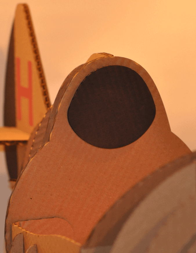
I started by having Henry choose the plane he wanted to be. I put together a mix of airplanes including a Cessna 172, P-40 Warhawk, F-86 Saber, and a P-47 Thunderbolt among others. Henry chose the Thunderbolt. For those of you who are not familiar with the Republic Aviation P-47, the airplane is a World War II fighter built from 1941-1945. Designed by Alexander Kartveli, the Fighter-Bomber was produced in two main variants throughout the war. The P-47 Razorback produced in the early years and had a cockpit that was integrated into the fuselage spine. This gave the pilot better rear protection but limited rear visibility. The P-47D-26 variant and later had a bubble top canopy allowing for greater rear facing visibility. The bubble top also had a thick armor plate behind the pilot seat allowing for rearward protection. The Razorback version was chosen as this added more character to the costume.
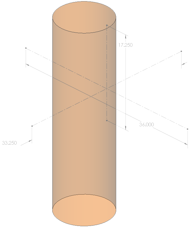
Henry is 35” tall and 10” across at the shoulders. This gave me a reference for the size and scale of the plane. I quickly started in SOLIDWORKS by creating a cylinder “Henry” size. The cylinder allowed the P-47 “three view” I borrowed from the internet to be scaled appropriately. I learned that if I wanted to keep the plane’s features such as the fuselage scaled to Henry’s size the rear fuselage and empennage would be 7 feet long. Obviously this was not going to work.
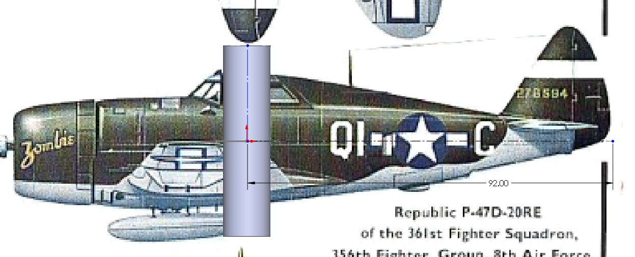
I decided to do a “cartoon scale” version of the plane keeping it to around a 36” wingspan, and 33” long. The main goal is to have a costume that has all the features of the real plane but is sized for Henry. The costume has to be light in weight and encourage mobility. I decided to use cardboard for the material and chose 3/16” thick sheets commercially available through most office stores.
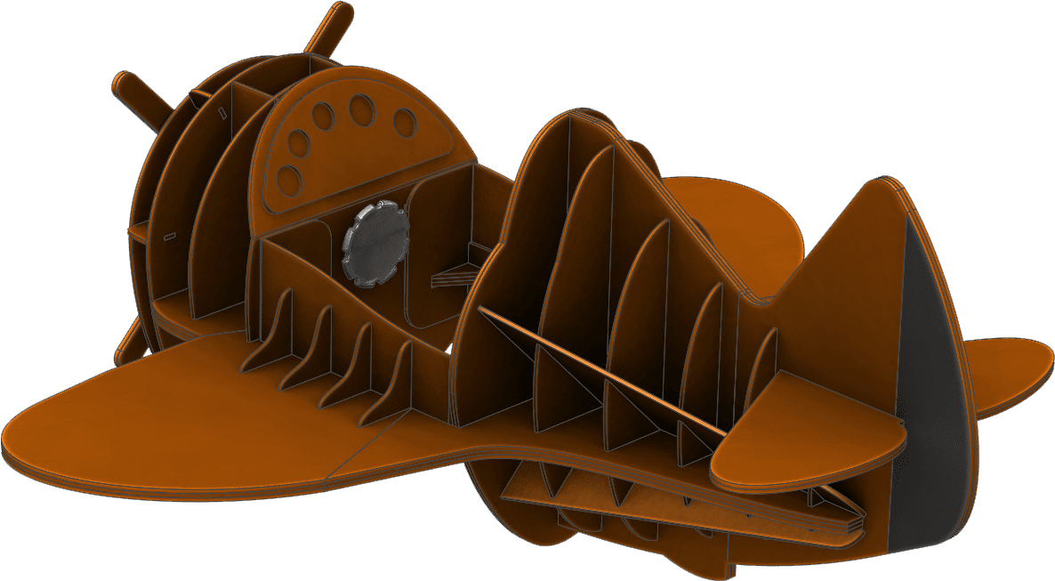
The model was designed as a multi-body part. This modeling methodology lends itself to geometry that contains references from component to component, allowing the generation of interconnecting parts easier and faster. The reference cylinder remained in my model, and I laid out the major overall dimensions for the length, wingspan, and height of the tail.
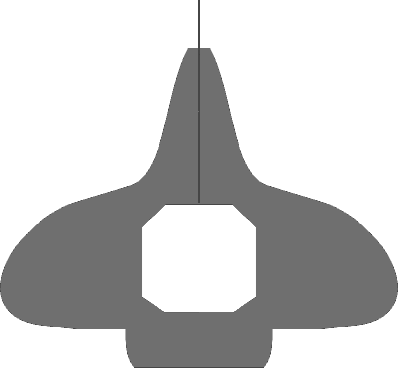
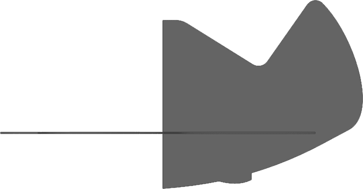
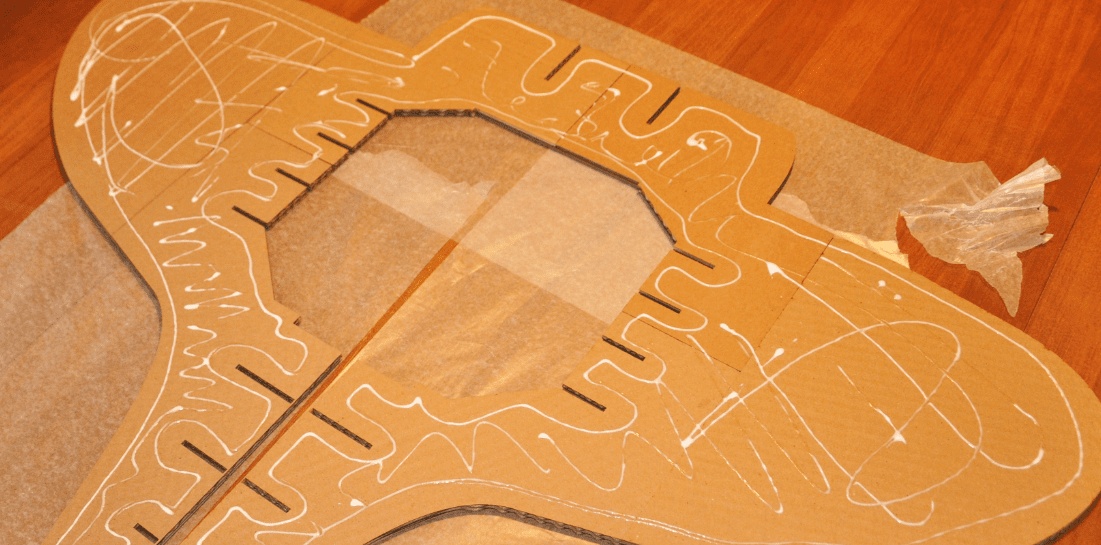
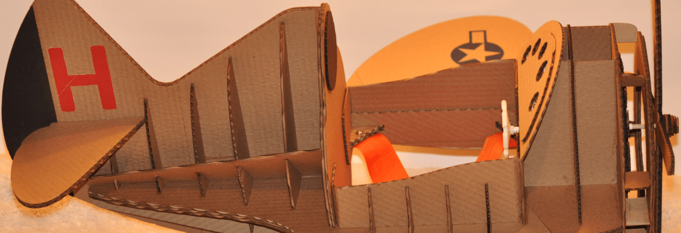
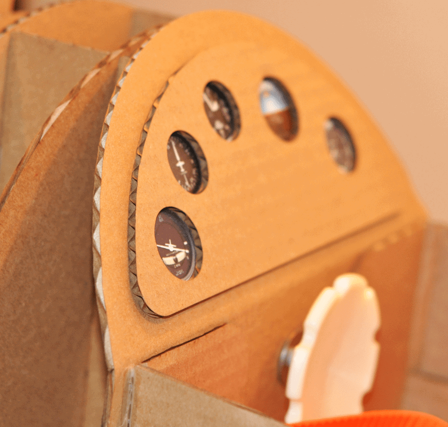
I started by laying out the wing profile making quick use of the dynamic mirror command. Because the wing will connect the front and rear fuselage sections the wing will be a laminate of three layers of cardboard. This will add rigidity to the structure, and give the plane a resistance to any unwanted bends, and dents. Once the wing was laid out accommodating the 10” diameter cylinder at the cockpit location, the next step was to tackle the fuselage and rudder portion of the P-47. I wanted to keep the tail as scale as possible, and keep details in profile like the underside turbo-supercharger outlet door (the little bump on the bottom). Interference was built into the model as I had not yet determined how the parts would slot together.
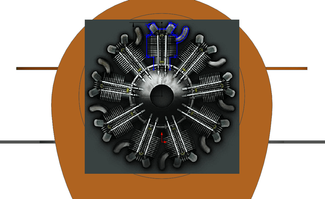
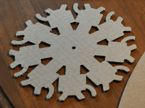
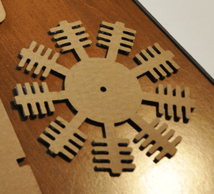
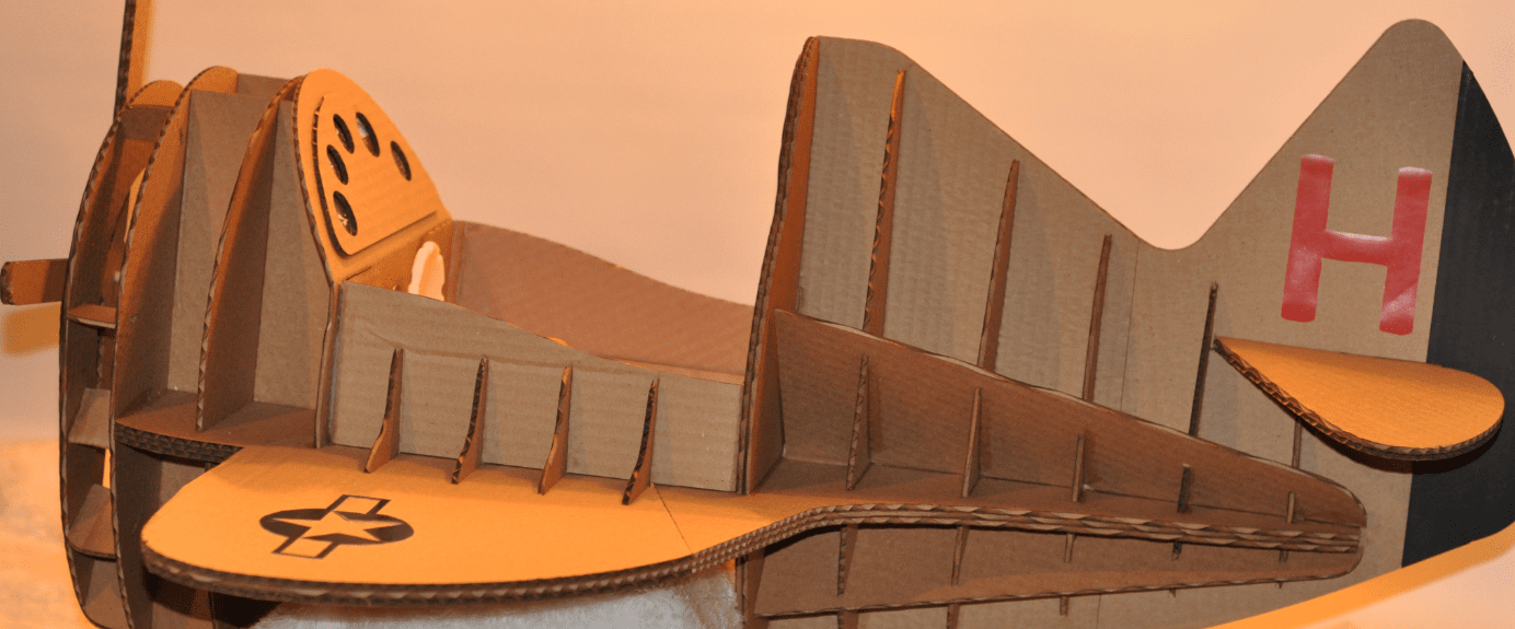
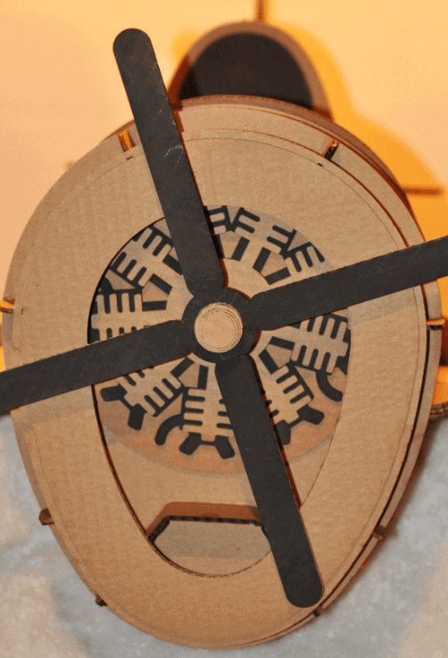
Throughout the model I paid close attention to the details of the real P-47 and tried to incorporate them into the costume. For example the P-47 was designed around a 2000 Hp. 18 cylinder Pratt & Whitney Double Wasp radial engine. Using a sketch picture I was able to scale a front view of the real engine. I used three layers of cardboard to layout the detail of the costume’s dummy engine.

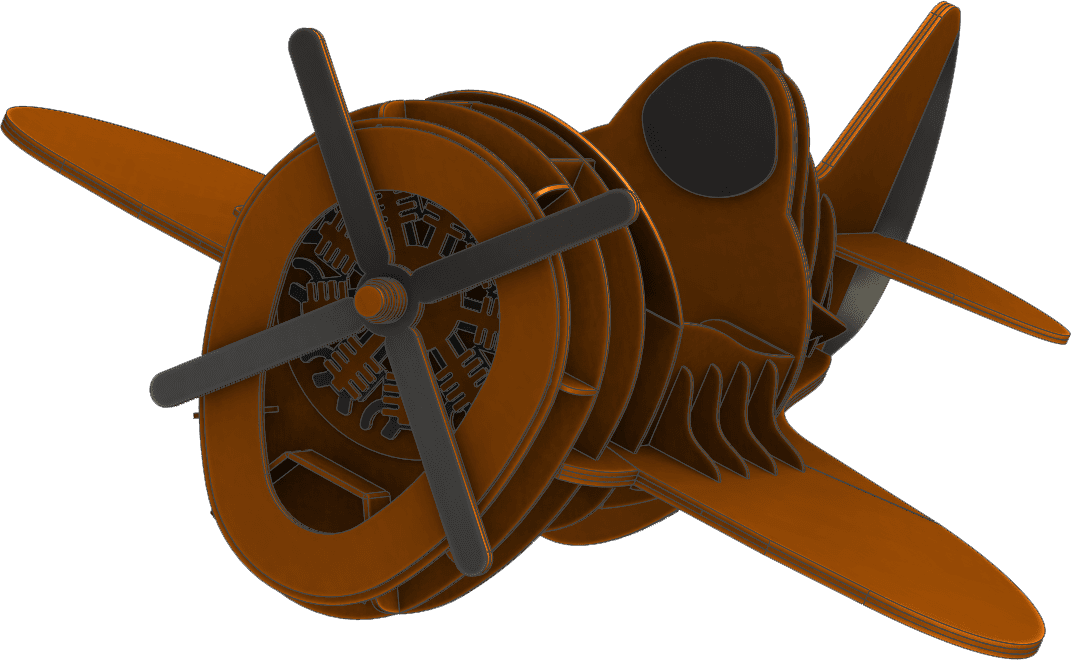
In an attempt to keep the lines of the original aircraft, the elevator was inserted via a slot in the tail and then covered by outer layers, leaving no open slot. A must-have feature of the costume is a spinning propeller. To do this I used a ¼” wood dowel to connect the propeller to a 3D printed propeller handle that resides inside the cockpit.
Because the design was a multi-body part it was easy to add the corresponding slots on all of the bodies that need to fit together. I used sketch relations to link the slot cuts to the part thickness. This design intent is important later. The slots are at a zero tolerance fit to the parts to ensure the structure holds tightly together. The parts are all self fixturing taking the guess work out of the assembly process.
Once I was satisfied with the design I needed to figure out how to get the parts cut out of the cardboard sheets. I quickly generated DXFs from the individual bodies by right-clicking on the body, choosing “Export to DXF/ DWG”. I was able to combine all of the part profiles into a single DXF using DraftSight. I researched several online companies that could cut the parts, however, they were very costly and supplied their own cardboard. I was on a path to cutting all of this out by hand. This would have been long and tedious. Fortunately I found someone who could help.
Chmura Custom Woodworks, local company to 3DVision/Cleveland came to the rescue. I contacted Bryan Chmura regarding the use of his laser table. I initially sent Bryan a 3d view of the project. Bryan was excited about the design and asked me to send the DXF. Within a couple of hours he provided a very reasonable quote for the job. The following week I dropped of the cardboard sheets for Chmura Custom Woodworks to cut the parts. Bryan did one thing that I forgot to do – he checked the sheet thickness. This was a crucial detail that I expected to be the true 3/16” dimension. In reality the sheets had been compressed from shipping and handling to a nominal 0.15”. This meant that my slots were too large and my part thickness was incorrect. I quickly modified the airplane design in SOLIDWORKS to change the sizes accordingly .
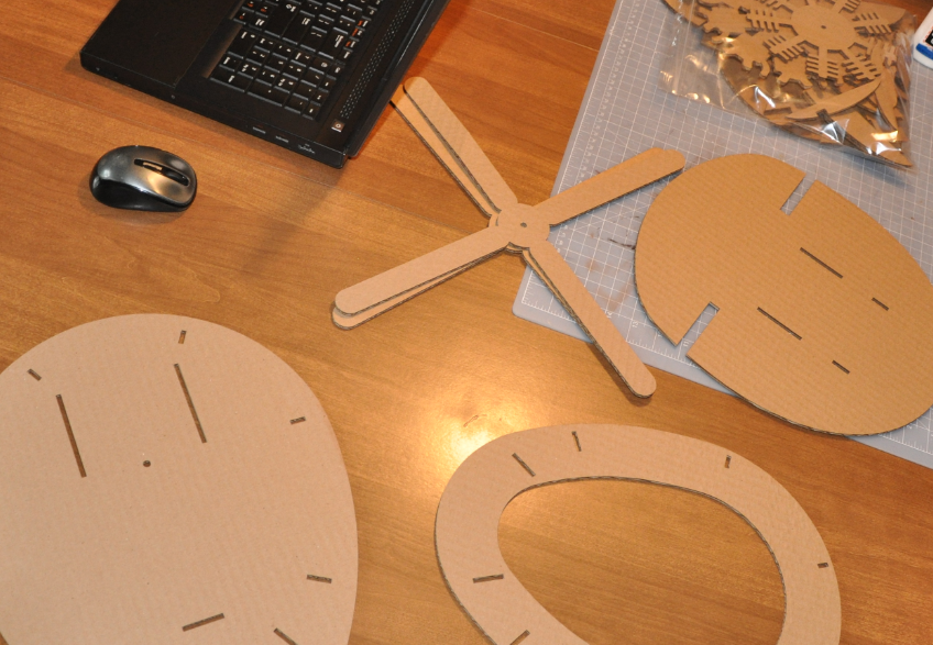
Here is where the design intent and sketch relations in SOLIDWORKS really shined. Within minutes I was able to change the model to accommodate the new part width. The slot cuts all updated as expected. I was able to generate the updated DXF for Bryan in under an hour so Chmura Custom Woodworks could cut parts the next day. If you have never laser burned anything before it is worth looking into as the parts exceeded my expectations and were better than I could have cut by hand.
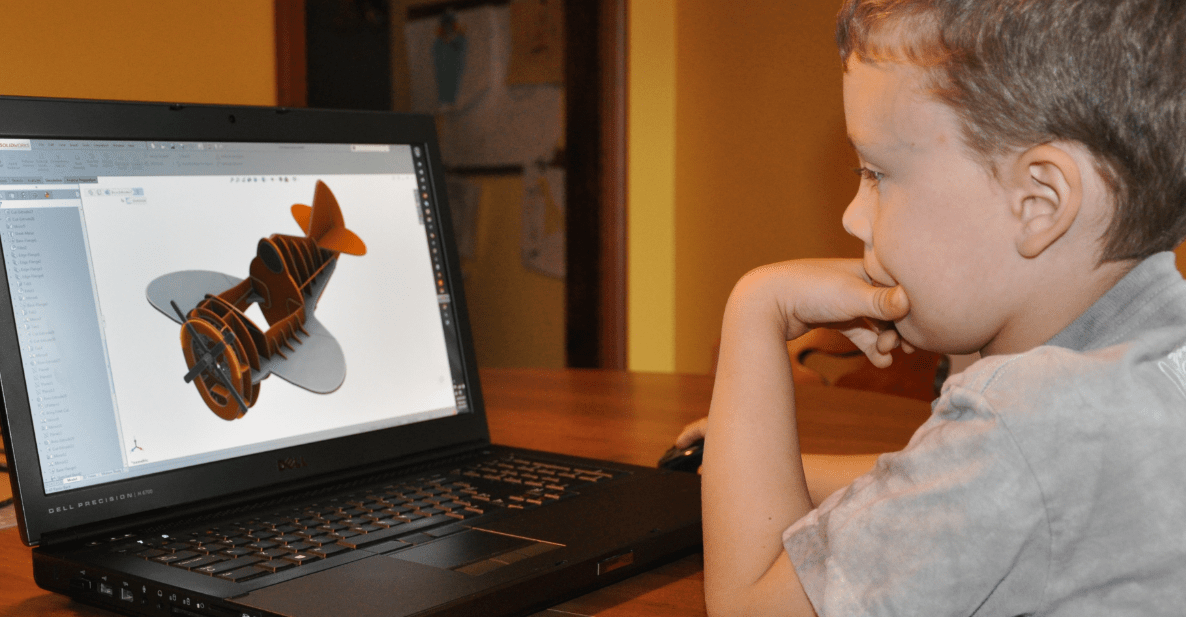
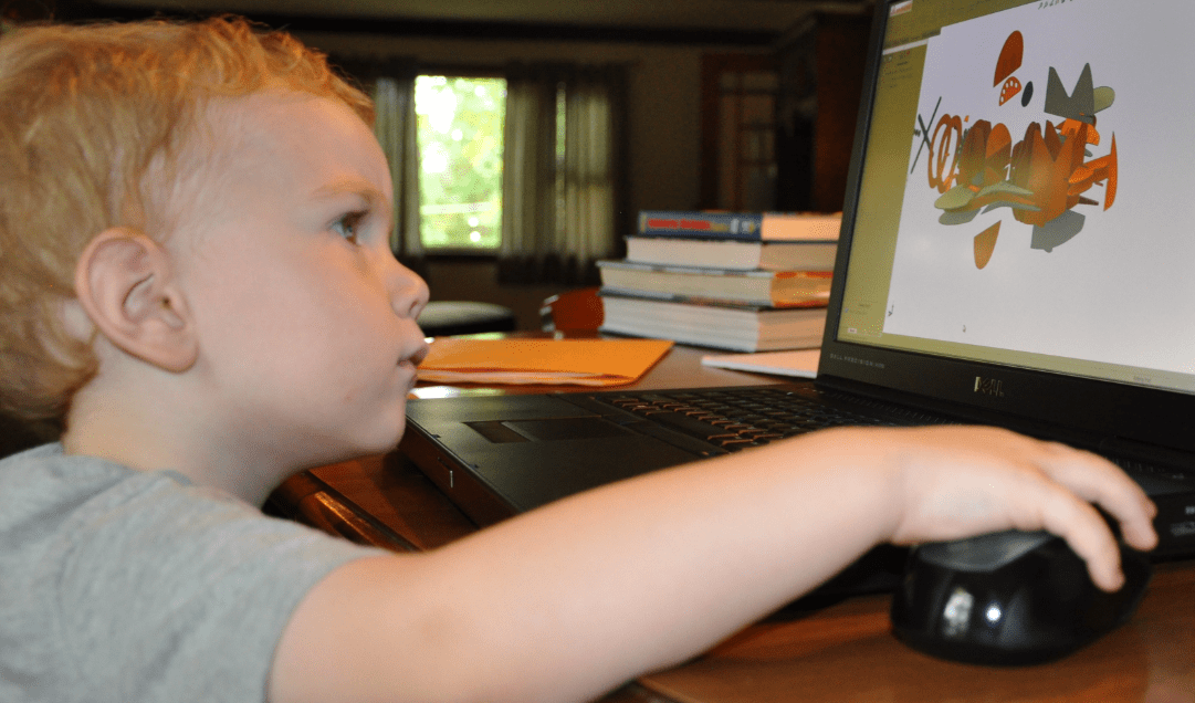
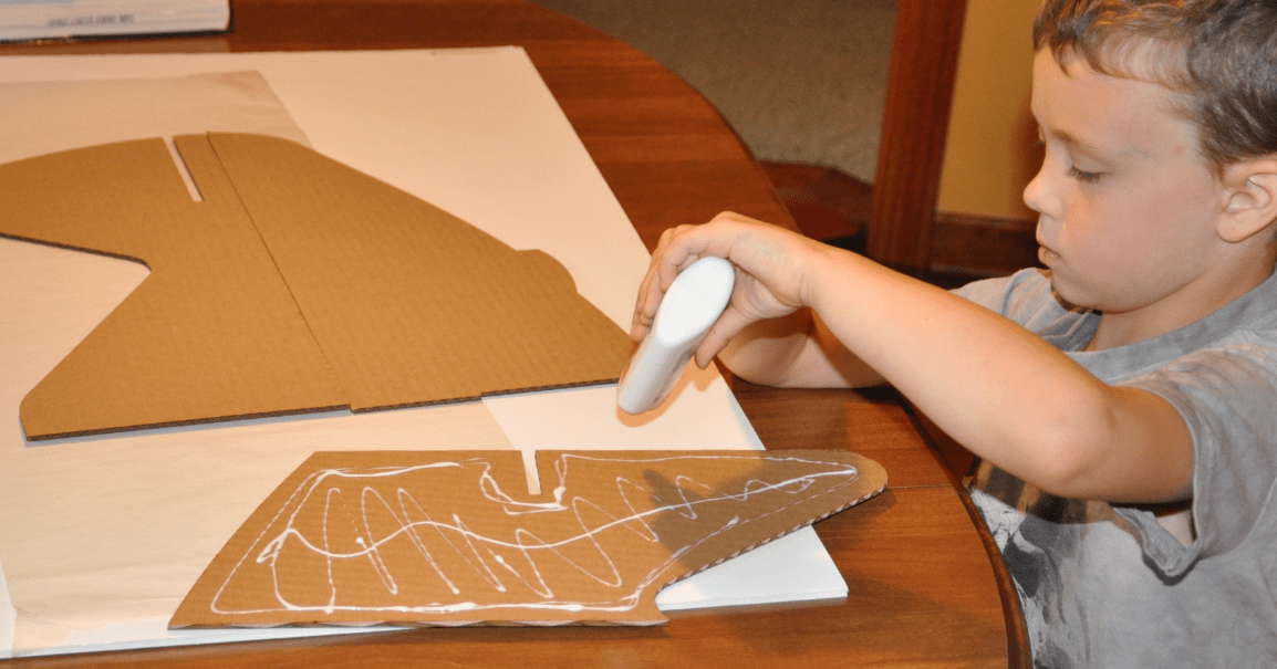
The best part of this project was building the costume with my sons. Nothing gets the kids excited more than building something. We started by reviewing how the model was put together in SOLIDWORKS. Matthew my 5 year old really investigated the model and was in awe of how the geometry went from computer to tangible parts.
We gathered the supplies and dove in. I started by taking pictures to make an instruction manual to show the assembly steps, but quickly abandoned the idea as it took me too many tries to get a good photograph. Instead, I decided to leverage the model I already created in SOLIDWORKS, and generate the instruction steps in SOLIDWORKS Composer. Composer proved to be easy to learn and leverage. I finished the instructions using Microsoft Publisher. The PDF instruction set is available below. The use of Elmers white glue-all was a good choice because, in some cases, there was more glue than cardboard when the boys helped. The glue also dries slowly allowing the parts to be repositioned making sure everything was set and aligned properly.
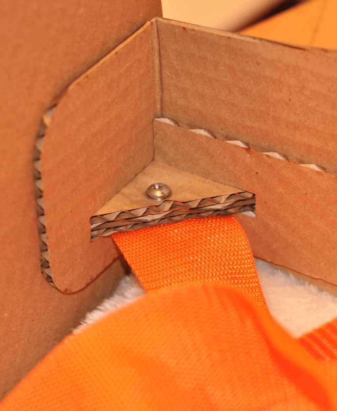
Once the bulk of the structure was assembled the suspenders were added to the corner blocks in the cockpit(not shown in the instructions).
The end results took a little over a week to complete only working less than an hour a day. However the wait was well worth the outcome.
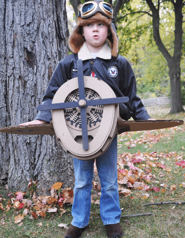
Of course like all two year olds Henry does not sit still long enough to get a good picture of him in the costume. He however has a blast running in the yard making airplane engine sounds. Matthew volunteered to have his picture taken with the costume.
With SOLIDWORKS I was able to create a super cool, and unique costume. The project created memories for me and my kids while getting them excited about engineering. What more could I ask for?