Stratasys 3D Printing: 3rd Party Software to Verify and Repair STL’s
3rd Party Software to Verify and Repair STL’s
Occasionally you may come across a part that comes out of your 3D printer looking horrible in quality. There are particular things within these defects that can help tip you off as to what is wrong and if it is your machine or your file that heeds help.
If you end up with a part that has shards of material jetting out of it or through the support, generally triangle in shape, it is a problem with your STL file. Holes, open areas, or even gaps in parts can become filled with 3D printing model material that was never designed to be there. The most confusing part of it all is that once the STL is produced, good or bad, you will not be able to tell if it is good unless it is tested through software or a failed print is produced.
There are several ways to verify and fix your files and I will show you how you can go about checking and fixing files. First you need to create your STL files, unless you receive them from customers, with the highest output settings to get a good file without cause issues within the software. You should also relay these settings to your provider to get the best possible part quality.
In the CAD package, when exporting to STL, you may see parameters for chord height, deviation, angle tolerance, or something similar. These are the parameters that affect the faceting of the STL. You don’t necessarily want to go too small on these parameters. The finer the STL, the larger the file is in size, which will affect processing time in Objet Studio as well could increase build time.
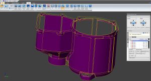
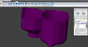
In this example, you can see the different way of going about verifying and fixing you model. Here is the part we are going to be taking a look at; it’s designed to be a cast part mainly using surfacing in the design phase.
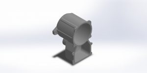
As you can see, everything looks fine here and appears to be a good solid file inside of SOLIDWORKS. But if we look into this more, we will find this part was constructed of 551 solid bodies or separate pieces that have not been joined together. Even if you have mating surfaces in the build, it can cause the output of the STL to split these areas if they aren’t joined. The STL file will save out fine usually even if the design isn’t adequate for printing. In SOLIDWORKS, and any other cad software, you will want to configure the settings to get the best results in quality and processing speed.
To do this in SOLIDWORKS you will need go to File > Save As then select STL from the file type drop down menu. Now, before you hit the save button, we need to find the box to the lower right hand side that says Options. Click that and in that window change the Export Options as follows. Output as; Binary, Resolution; Custom, Deviation Tolerance; somewhere less than .003, Angle Tolerance; 5 degrees. If this is part is from an assembly you will want to check the box “Save all components of an assembly in a single file”, so that you come out with 1 file instead of multiple files.
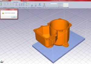
Once your file is created, you will normally bring it into Objet Studio program, and if you run the Verify tool, it will check to see if it can spot any errors in the part. If it does, it will highlight the part in another color other than the default color for the material you have selected. In this case, it turns our part orange to indicate it has issues.
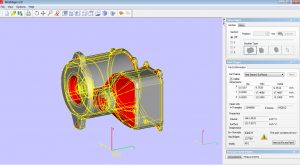
To see how many errors are within the part and where they are a good, free, tool is one called MiniMagics by Materialize. You can use this to view STL’s but will not do anything to help fix them. Now you can purchase a full blown version of Magics which can do all sorts of model manipulation and fix these issues.
After a quick scan, we can see all those solid bodies ended up being an issue because the edges are joined. MiniMagics found this to have 636,477 Inverted Normals, which are triangles in your STL mesh that are facing the wrong way. 137,760 Bad Edges, and 401 shells. You want to reduce the number of shells down to as few as possible to reduce the amount of bodies that make up a part so there is no potential for gaps between joining edges.
To actually fix this part, we have used yet another 3rd party program called Solidview this time. When we bring this part in, it just confirms what we have already seen in Minimagics in that the surface data is insufficient for printing.
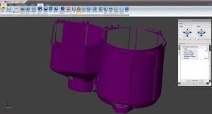
This repair feature breaks the part out in depth though and shows us all the issues in detail and what needs to be repaired. The shells it found were a little more than Minimagics, but is fairly close to the estimate it gave. We then can run the automatic repair, which goes in further and shows the areas it will attempt to fix.
This repair did an excellent job stepping through and fixing each individual area one by one, which gave us a water tight model we can then take back to our printer.
After the repair is done, you can go though and see which of the features it fixed. And if it was not able to auto fix them in that pass, you can go back and focus on manually fixing that area.
3rd party software is a critical piece of equipment to have to fix and verify your models especially if you have design work being done out of house or are doing a lot of surface modeling. There are many ways to go about this but we only touched on a couple we had handy here at the time.
Dominick Damato
Field Service Technician
Computer Aided Technology