Stratasys 3D Printing: Discovering Your 3D Printer’s Capabilities – Part 2
Discovering Your 3D Printer’s Capabilities – Part 2
This is the 2nd of a series on ideas to understand the capabilities and limitations of your 3D Printer. When you know what your machine can achieve, it can be applied to significantly aid your part design as well as throughput and quality.
When 3D printing holes with FDM (Fused Deposition Modeling) it is always desirable to position the hole axis perpendicular to the platform. Unfortunately some designs (channels for wiring ,tubing, fluid, air, etc) require that the holes be sliced in a horizontal orientation. So, can supports be eliminated in these horizontal holes?
If you will remember from Part 1 of this series, structural supports are dependent on three variables: technology, material and layer thickness. This is especially true for horizontal holes, being assembled in layers. A horizontal hole, with the axis parallel with the build platform, is sliced into layers with half of the hole requiring an overhanging layer. As we previously discovered in Part 1 of this series, some overhangs can be built without a support structure. See Discovering your 3D Printer’s Capabilities – Part 1.
So the question becomes, “How large of a horizontal hole can be built without requiring support?”. A simple test part can show you what to expect.
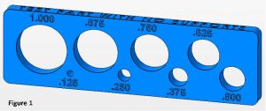
Creating a part with a series of holes (0.125 – 1.000 inch at 0.125 inch increments), positioning it as shown in Figure 1 and editing the parameters to build with no supports, will easily show the maximum unsupported hole that can be built for a particular technology, 3D print materials and layer thickness. The STL file shown here is available upon request from Mark.Abshire@cati.com.
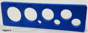
The part shown in Figure 2 was built with FDM using ABS material at .010 inch layers. Notice that even with no support, the part built without a crash, but some surfaces on the larger holes are ‘sagging’ and are not acceptable without supports. This gives you an idea of what size horizontal holes you can incorporate in your design to minimize support, build time and cost.
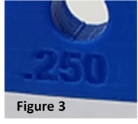
Also notice that the text, shown in Figure 3, built crisp and well defined, even being built standing up with no support. This is achievable because the text is recessed only .020 deep. When FDM is sliced at .010 layers, the typical default of the filament contour width is .020, by limiting the text to no more than 1 contour width the overhang can be built without supports.
In part 3 of this Discovering your 3D Printer’s Capabilities series we will discuss how to incorporate the techniques for the previous 2 blogs in our part design.
Mark Abshire
Application Engineer, Additive Manufacturing
Computer Aided Technology