SOLIDWORKS: Modeling Springs for Assemblies
Modeling Springs for SOLIDWORKS Assemblies
Why is my assembly so slow!
This is a topic that comes up a lot. No your SOLIDWORKS is not broken. Yes, maybe it was the latest Microsoft Security patch that they forced on us, but it is not always the fault of the software. More often than not, it comes down to modeling methodology and the amount of detail we are trying to cram into our models.
There is a time and a place for detail. Having highly detailed parts for piece part manufacturing is perfectly acceptable and necessary. Placing highly detailed parts into large assemblies can cause severe performance issues.
One of the best tools we have to see which components have the biggest impact on our assemblies is the assembly visualization tool. Please see our previous blog article: Why are my assemblies so slow? Let’s check the load on your video card
Recently I started investigating an assembly for a customer. One component that he has inserted multiple times was a helical spring. We know that helical features are major performance killers. So, how can we model these springs in an effective manner that will not kill our overall performance?
Let’s take a look at one of the springs.
Our initial file size is 1408 KB, but our Graphical triangles to display this is 69018.
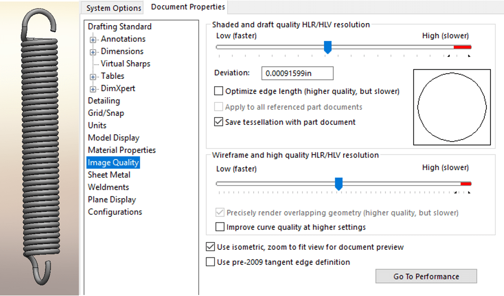
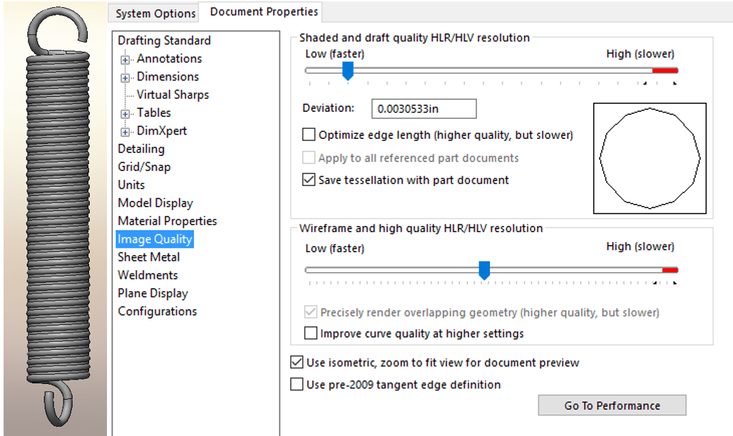
We also want to take a look at the image quality. The slider should be between ¼ and ½ of the way from the left side. Moving the slider to the right end (Red Zone) will cause exponential file size growth.
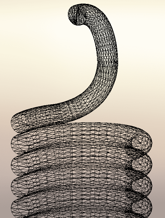
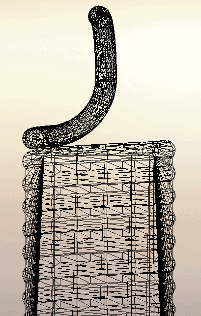
The reason our triangle count is so high is that we have to calculate the face curvatures all the way around each coil of the spring. Here is a cross section of what this mesh would look like:
To simplify this geometry, I am going to create a new configuration called SIMPLIFIED, and I am going to extrude a solid cylinder thru the center of the spring. This will reduce the curvature geometry that needs to be calculated.
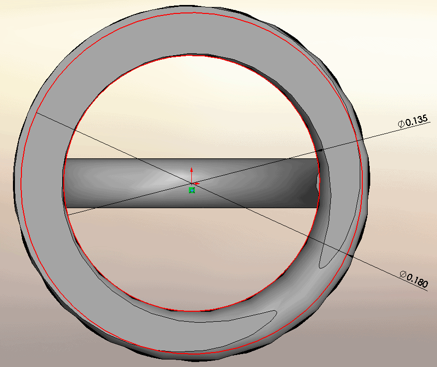
On this part, the top plane is in the middle of the spring. I am going to create a sketch on the top plane. I am going to create 2 circles. The first circle is going to be a hair smaller that the inside diameter of the spring. The second circle is going to be about .01” smaller that the outside of the spring (this value is just a guess).
Now we are going to extrude this in both directions so that it intersects with the last coil on each end of the spring. Make sure you merge the result.
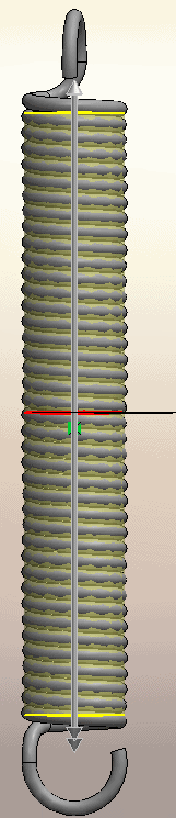
The result is a spring that still looks like our modeled spring, except you will not see the gaps between each coil.
The new file size is reduced to 543 KB (61% reduction). More importantly, the graphics triangles were reduced to 12362 (82% reduction).
Here is what the new graphics triangle image looks like:
So by merging 80% of the spring geometry into a single solid block, we can get significant file performance improvements. Just make sure when you insert your spring into the assembly that you use the simplified configuration.
Hope this helps when modeling springs for assemblies in SOLIDWORKS 2017.
Bryan Pawlak
Sr. Application Engineer
Computer Aided Technology