SOLIDWORKS 2017: Converting 2D to 3D
Converting 2D to 3D
This Blog article is going to be a picture heavy walk through of how to do a simple 2D to 3D conversion in SOLIDWORKS. This file is a DWG file, but this method works on DXF files as well.
Contents:
- 2D to 3D toolbar
- DXF/DWG Import tool
- Import options
- Converting 2D to 3D methodology
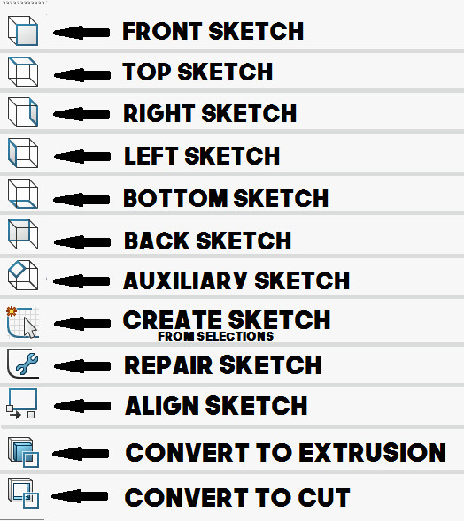
2D to 3D toolbar
We start by opening up our DWG/DXF just like we would any other file within SOLIDWORKS.
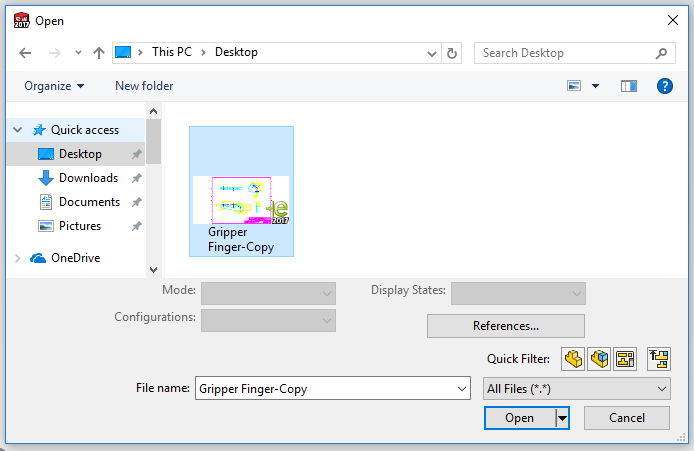
Once we OPEN the file, the Import tool pops up.
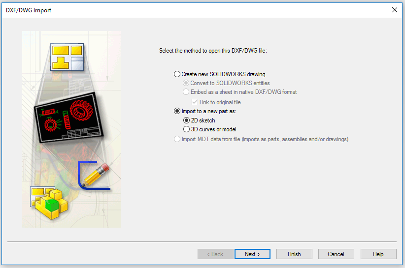
DXF/DWG Import Tool
The picture below is the tool you will see after you open your document. This tool gives us a few import options.
- Create new SOLIDWORKS Drawing
- Import to a new Part as either a 2D sketch or a 3D curve
For the conversion from 2D to 3D, we want to choose the option “Import to a new part as: 2D sketch”.
Then we can hit the NEXT button.
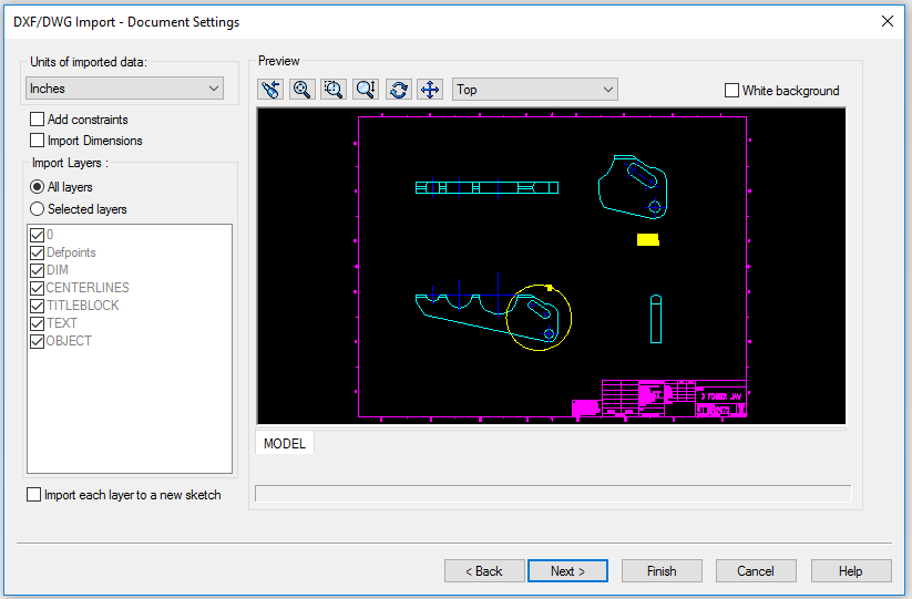
On the next screen, we will see our Document Settings options. On this page, we can choose to bring in all layers, or just a select few. Typically, we want to bring in all layers so that we can remove any excess of our own accord. Otherwise, when we do not include a layer, we might accidentally be leaving out a small line that is necessary to our sketch contour.
This page also gives us an option to add constraints and import dimensions if we would like. Bringing in dimensions is helpful to define how it was created, however it is good to note that neither the dimensions or the constraints fully define a 2D sketch you bring in. Example of bringing in both dimensions and constraints (aka relations) below.
**Constraints and Dimensions brought in below for example. **
We will leave those options cleared and hit our NEXT Button.
The second page is the Drawing Layer Mapping options. This page allows us to choose a few more import options such as; merge points closer than a value, merge overlapping entities, run repair sketch, define the sketches origin.
I recommend using the Merge points closer than .001 option, and the merge overlapping entities. Those two will help eliminate some potential contours that would otherwise need to be fixed.
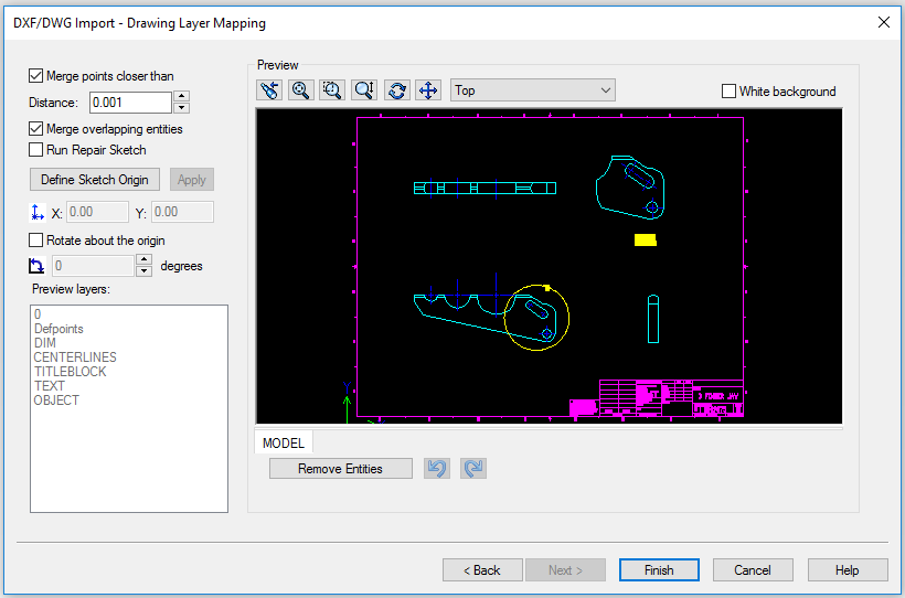
On this page, we can also Remove Entities by selecting entities in the preview box and hitting the Remove Entities button. This feature while being handy, makes it hard to see what it is you are selecting within the small preview window. By general rule, it’s good to leave all entities in the sketch, and remove what you do not desire once the sketch has been created in a part document.
**Example of removed entities within this tool below. **
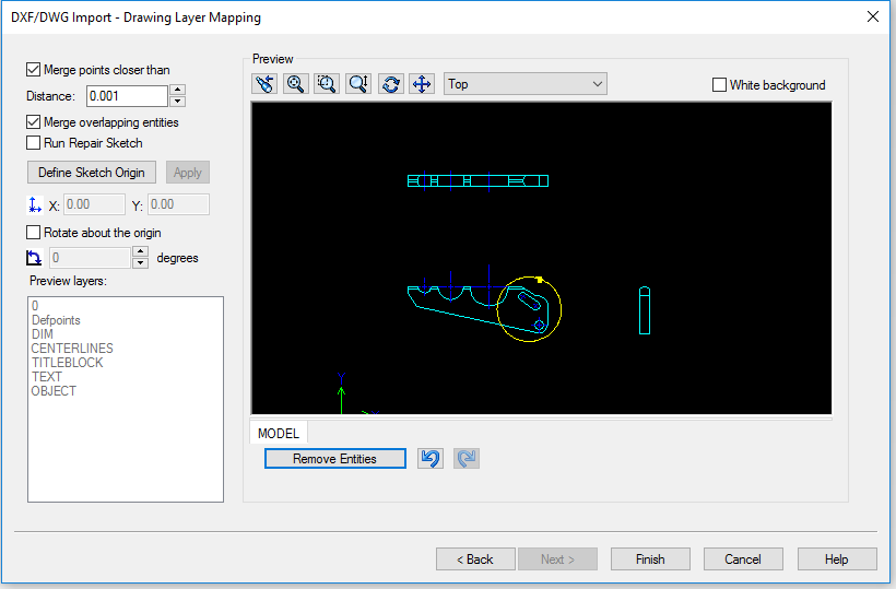
With our entities still all intact and our two merge options checked in, we will hit the FINISH button.
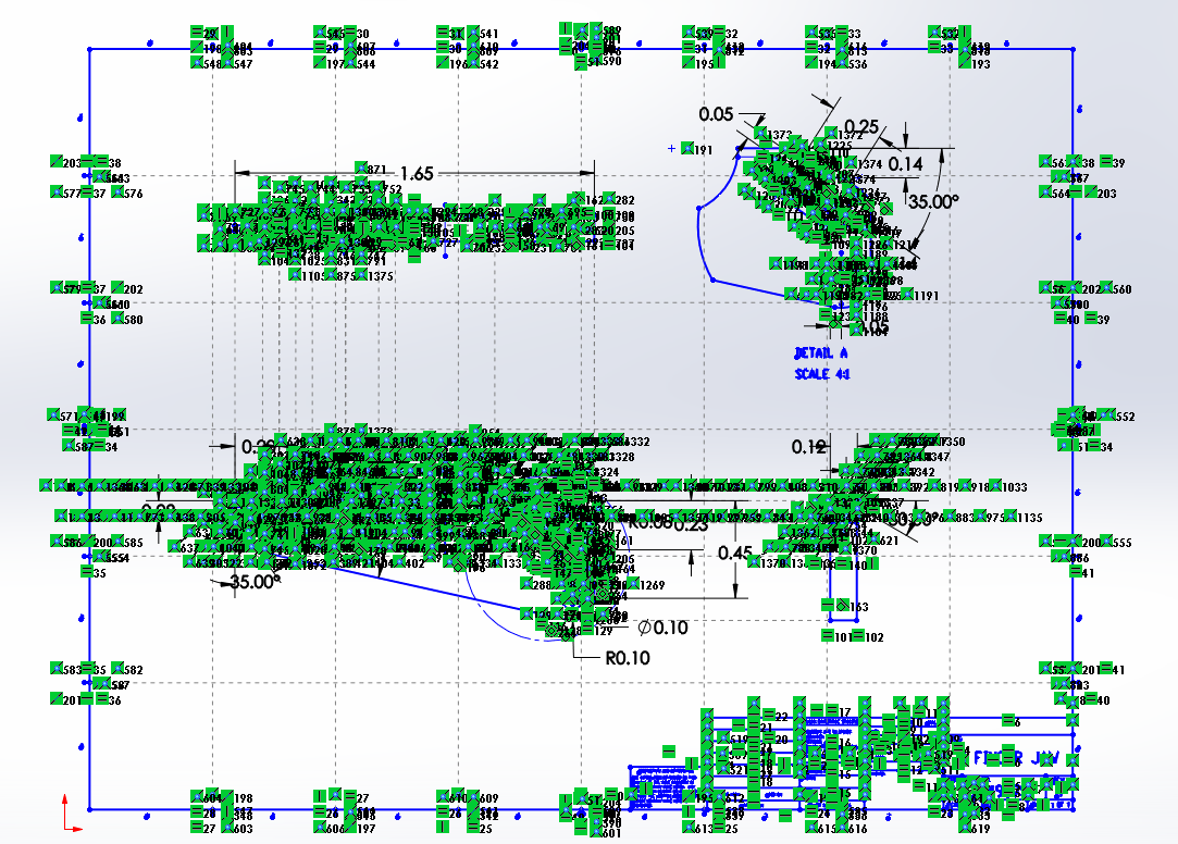
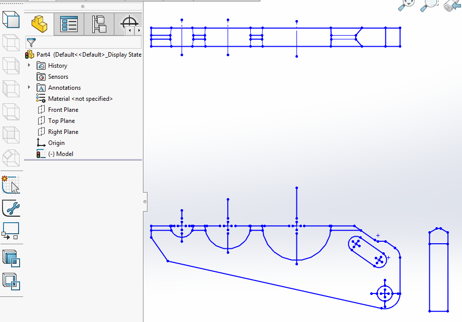
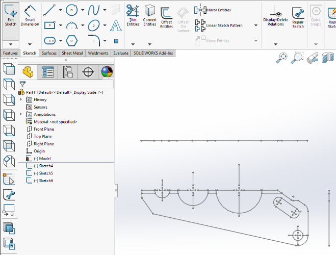
Below is the resulting 2D sketch created and inserted in a new part document.
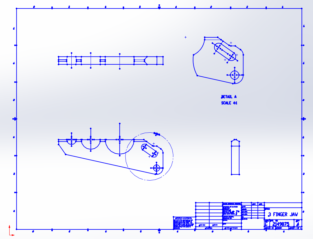
Now that we can see all our entities, we can remove what we don’t need, which in this case is the title block and the auxiliary view. We can do this simply by box selecting what we do not want and hitting delete on our keyboard.
The next step is to start defining our sketches, starting with what entities will be our Front Sketch.
Let’s examine our 2D to 3D toolbar again, you’ll notice that right now everything is contained within one sketch and all other view sketch options are unavailable, except for the Front Sketch.
Lets define our Front Sketch by box selecting all the Front View Entities and clicking the Front Sketch button on the top of the 2D to 3D Toolbar.
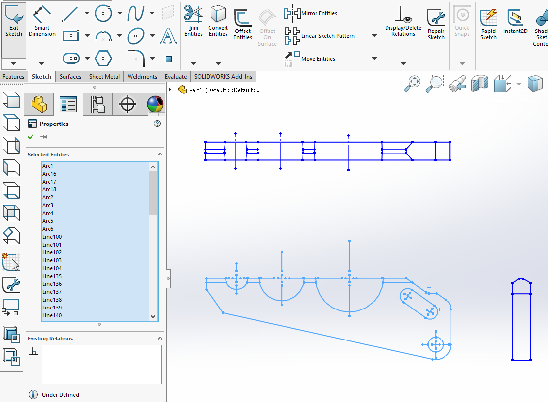
Those sketch entities are now moved onto the Front Sketch Plane.
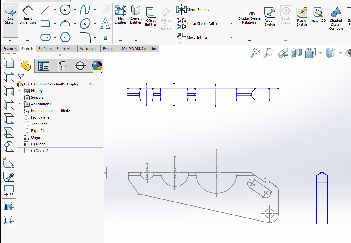
Now that we have designated a Front Sketch, you will notice we have a second sketch listed in the Feature Manager Tree.
Lets designate the Top Sketch and the Right Sketch next, using the same method; box select our entities and push the corresponding button in the toolbar.
**Below is the Top Sketch moves onto the Top Sketch Plane.**
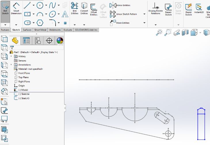
**Below is the Right Sketch moved onto the Right Sketch Plane.**
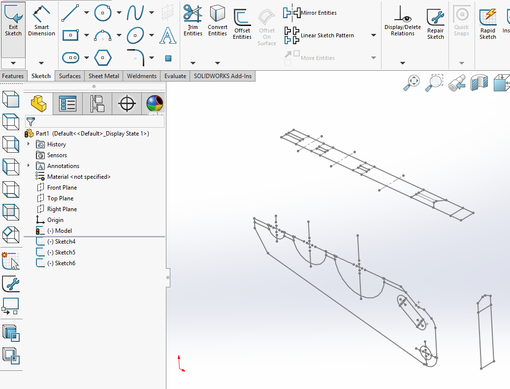
Our result at this point are 3 sketches in out Feature Manager Tree that are now on our corresponding planes. We aren’t ready to translate to 3D yet however, because we still need to ALIGN our views to the origin and to each other.
Aligning Sketches
There are a couple important things to remember when aligning sketches.
- The first selection you make will get moved (aka aligned) to the second selection.
- You need to align in 2 directions, essentially making a coincident relationship to 2 planes.
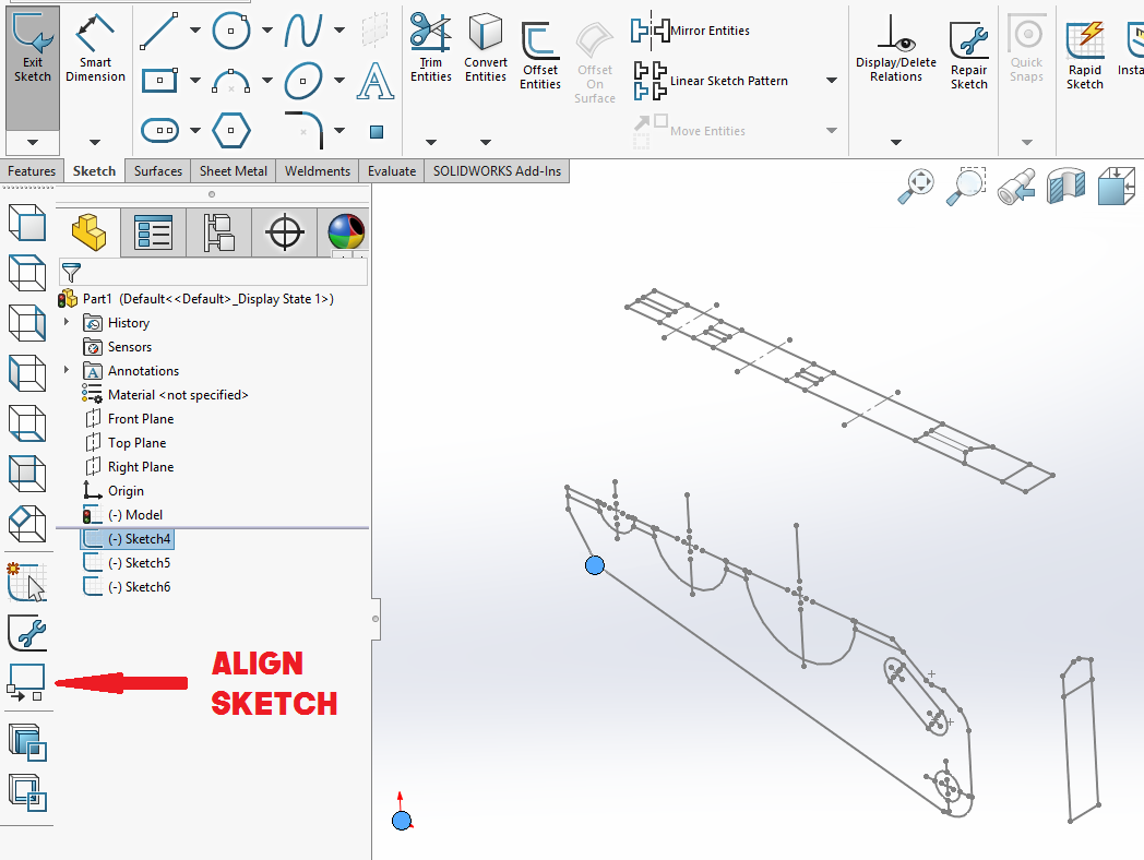
**I will exaggerate my selections in these images, so that they are easy to identify.**
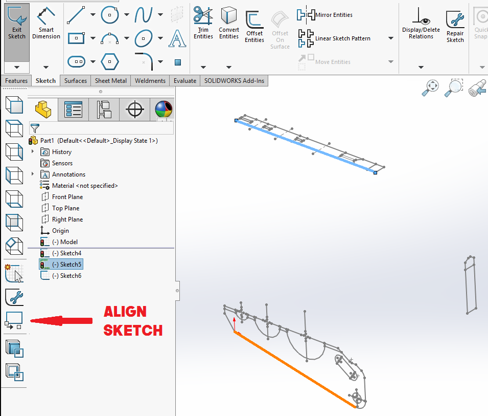
STEP 1: Align the Front Sketch to the Origin by selecting the point we want from the Front Sketch, then selecting the origin.
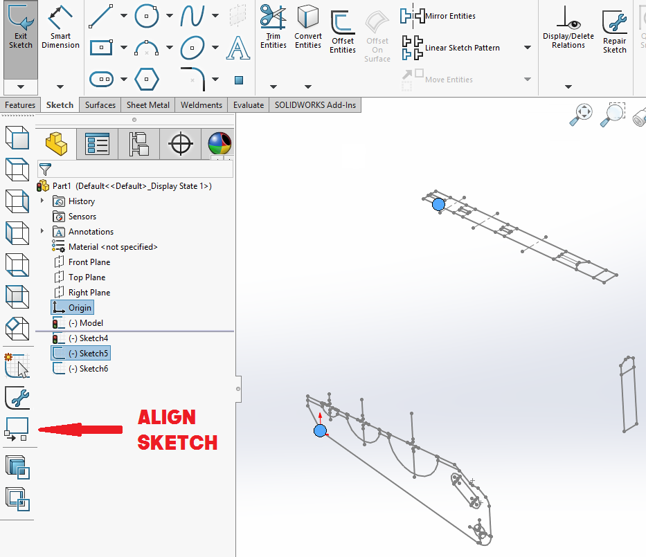
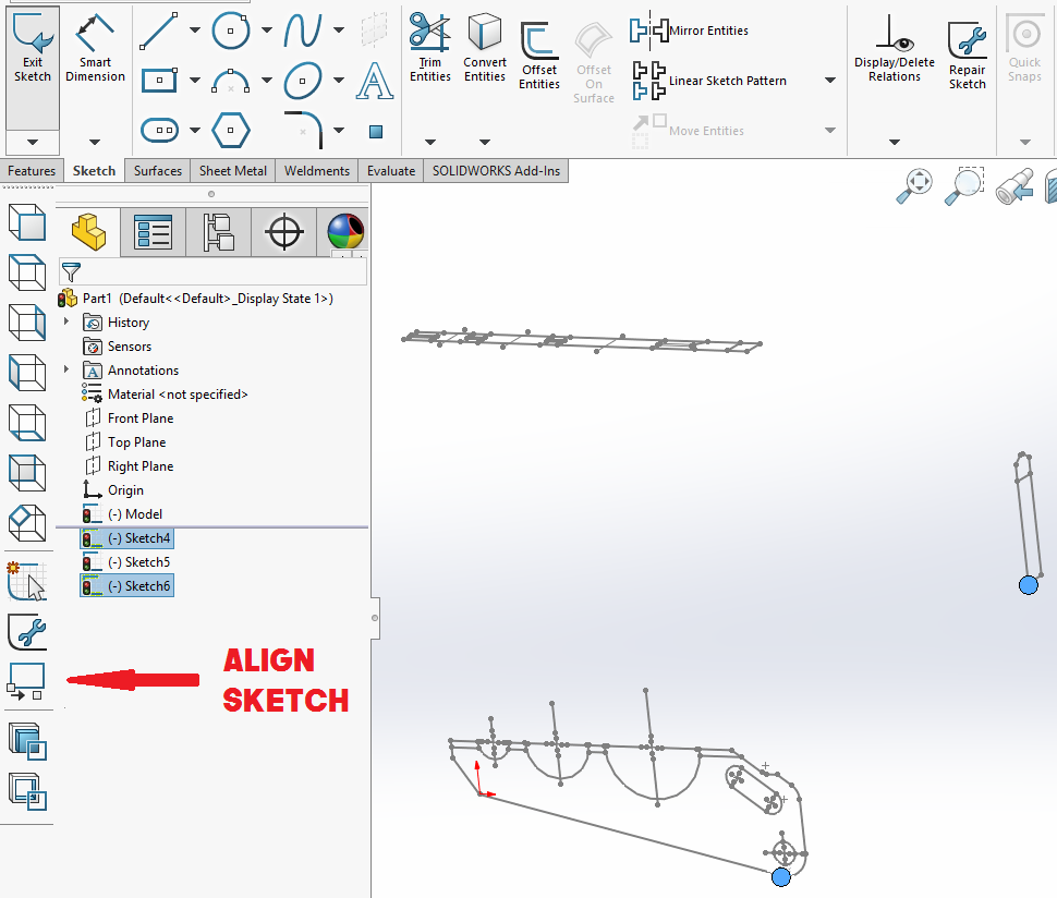
STEP 2: Align the Top Sketch to the Front sketch.
REMEMBER, we want to select our Top Sketch entity FIRST because we want that sketch to be the one to move over in alignment with the Front sketch position.
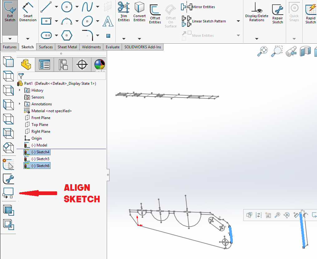
STEP 3: Align the Front Sketch along our second plane using sketch line entities.
STEP 4: Align the Right Sketch with the Front Sketch.
STEP 5: Align the Right Sketch with the Front Plane to our second defining plane using line sketch entities.
Converting from 2D to 3D
When using the 2D to 3D toolbar to convert a sketch into an extrusion, the most important thing to remember is that you must select the sketch you want to convert to an extrusion FIRST.
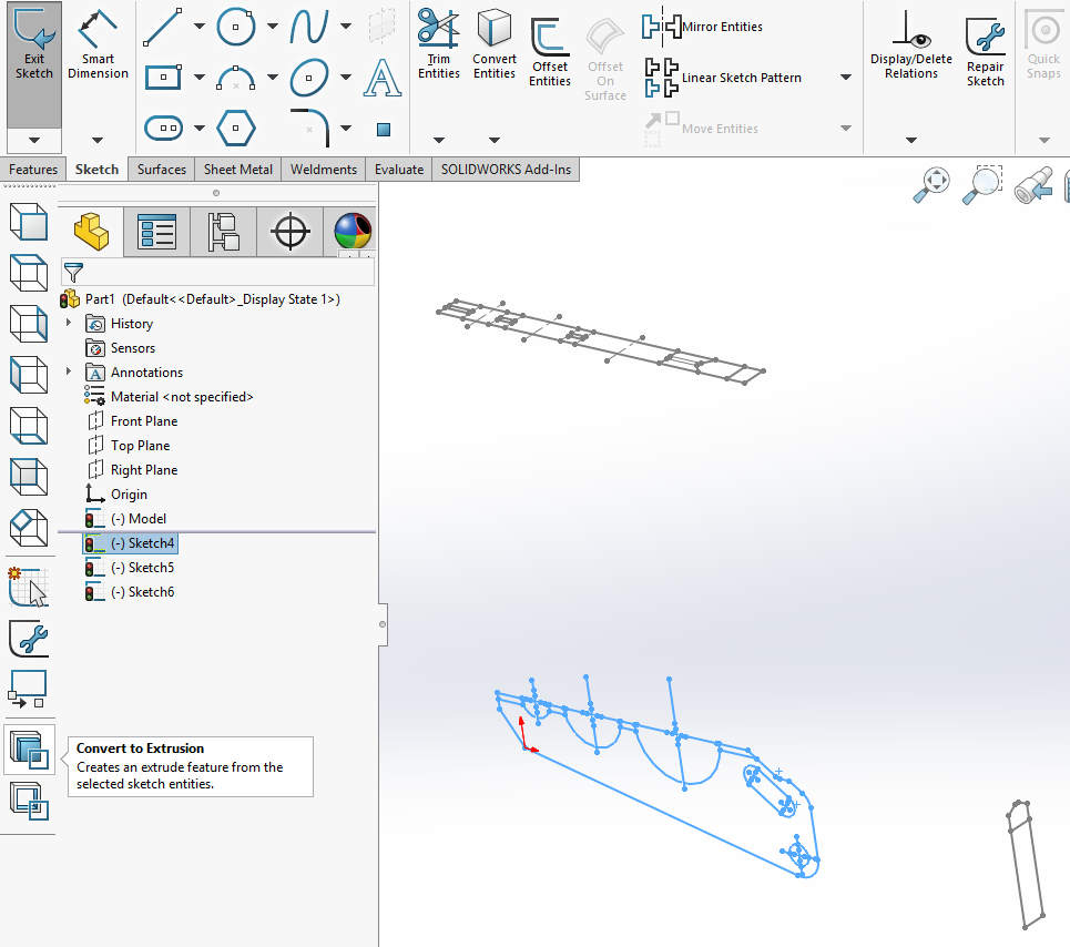
Once you hit the Convert to Extrusion button, the property manager for a Boss-Extrude pops up. Not having actual dimensions might trip up a non SOLIDWORKS user, but we have our handy direction option “up to vertex”. This way we can just select the vertex out of our Top Sketch, since this sketch defines the thickness of our part.
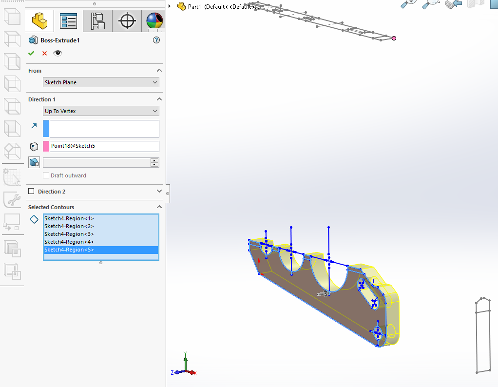
The last thing to do before we process this command, is to make sure we have selected all the contours we want to extrude. Lets activate our “Contour Selection” dialog box and grab our necessary contours. This example has some small areas at the tip of each tooth that could be easy to miss.
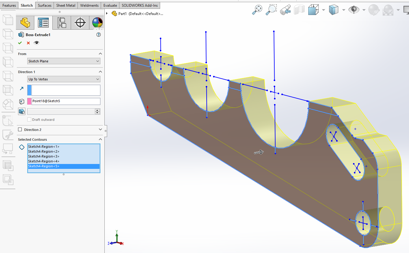
Now that we have our thickness set using our UP TO VERTEX direction and we have selected all our contours, we can accept this command.
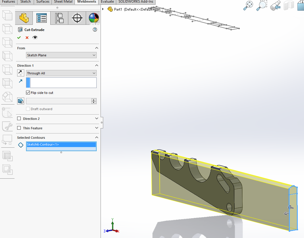
Convert to Cut
Next, for this example, we need to convert a sketch to cut. The Right Sketch shows a chamfer on either side of the top face. We can use the Right Sketch to Convert to Cut, but instead of cutting inward we can cut outward by checking in the option to “Flip Side to Cut”.
REMEMBER, we need to select the sketch we want to convert first, then hit the convert button. I select my sketch out of the Feature Manager Tree.
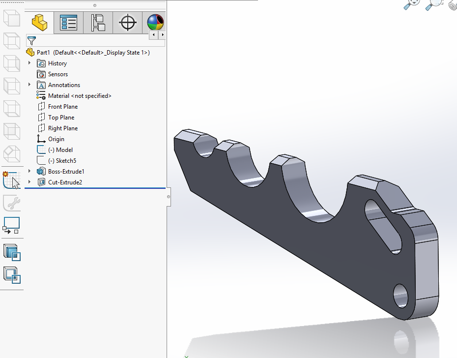
Our part is officially converted from 2D to 3D!!!!!
BONUS Material
Auxiliary Sketches are slightly trickier to place on a Plane.
Placing an Auxiliary Sketch:
- Box select all the entities to be placed in the auxiliary view.
- Select a sketch line from the front sketch that runs parallel to where the auxiliary plane should be (use ctrl for multiple selections).
- Click the auxiliary sketch button and watch the sketch move to a plane parallel to that sketch line you chose.
Courtney Roemer
Applications Engineer
Computer Aided Technology