INSPECTING 3D Printed Prototypes with 3D Scanner Technology
INSPECTING 3D Printed Prototypes with 3D Scanner Technology
Within the last 10 years CAD software has risen to new heights, giving the user more control over their designs and allowing them to create more curved surfaces on parts. In the manufacturing world, manufacturing processes have evolved to meet the designers demands breaking through walls of tighter tolerances and high complexity.
What does this all mean? Well, if you’re you in the QC department, this means you have an unrealistic task of inspecting parts using traditional methods. For many decades, inspecting parts with calipers, micrometers, straight bars and even rulers have sufficed, but it wasn’t until CAD software gave users the ease-of-use to create curvilinear surfaces that these traditional methods of measurements became insufficient. Even if a feature can be inspected, the inspection accuracy is not high enough and it cannot meet the requirement of time and operation difficulty in practice.
Introducing the next technological advancement in quality control; 3D scanning. 3D scanning has brought a whole new way of inspecting parts to the table. With metrology-grade accuracy, regardless of complexity, and the ability to acquire half a million measurements per second effectively, 3D scanners have become the new go to tool in the tool box. With plugin play ability and virtually little to no learning curve, the ability to 3D scan a part and create an inspection report reduces the process exponentially.
Let’s take a look at a continuation of an earlier blog Reverse Engineering with 3D Scanners and SOLIDWORKS.
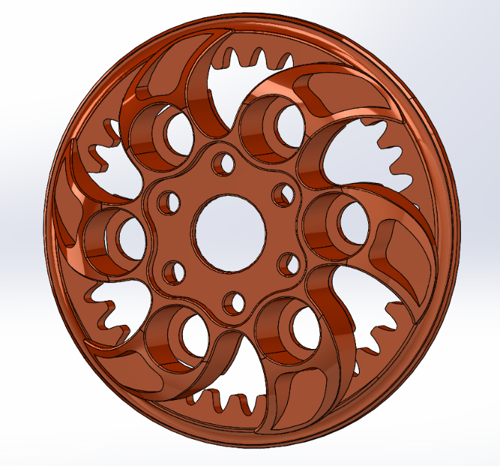
In this project, we 3D scanned a legacy part that was no longer in production to re-create a CAD model with manufacturable drawings. One of the added benefits of using a 3D scanner was the ability to capture accurate curved surfaces.
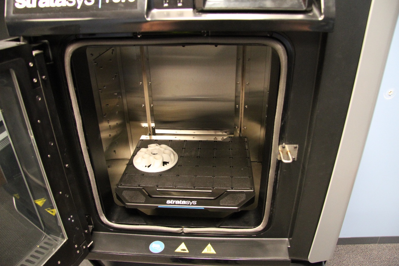
The next step would be to create a 3D printed prototype to verify our design. This was accomplished on the F370 series by Stratasys.
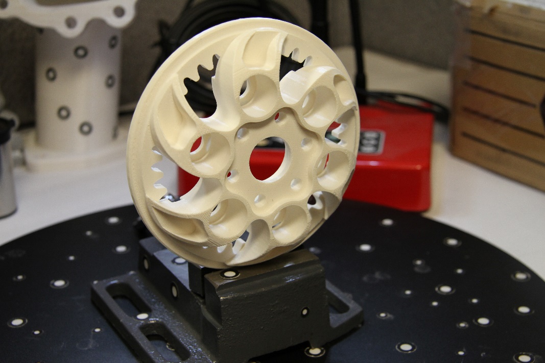
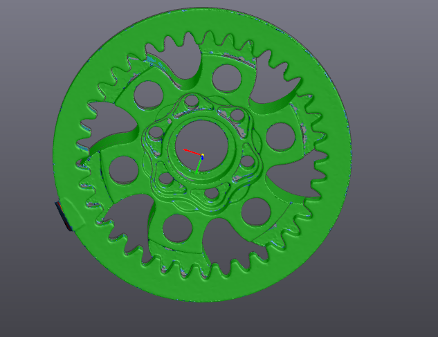
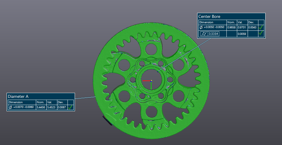
Next we used CREAFORMS HandyScan 700 to scan the 3D printed part and compare it to the CAD model in VxInspect.
Utilizing VxInspect to align the CAD model and the scan data to their respective datums, we are able to see an overall deviation of 0.005” plus material, which falls within the resolution of the 3D printer and could be used for a rough casting.
Going a little deeper into the inspection process, we could see that a few of the key features fit within a rough casting tolerance as well.
Let’s face it, as more and more breakthroughs in CAD design start to emerge and shape the industry of production, quality control methods need to diverge from archaic ways and restructure for future needs. As Steve Jobs once said: “You can’t look at the competition and say you’re going to do it better. You have to look at the competition and say you’re going to do it differently”.
For more information on VxInspect or other 3D scanning solution, check back into CATI’s Tech notes for future blogs.
Thanks for reading and remember: The engineer’s first problem in any design situation is to discover what the problem really is.
Bob Renella
Application Engineer
Computer Aided Technology