SOLIDWORKS: Setup and Troubleshooting Visualize Boost
Setup and Troubleshooting SOLIDWORKS Visualize Boost
Back in November, Jordan wrote about Installing and configuring Visualize Boost; today I want to talk about how to setup boost according to your network, and what to do when boost doesn’t work, or your network doesn’t support some features of Boost. While Boost can be a very powerful time saving addition to rendering with SOLIDWORKS Visualize, it can also be finicky to setup and get working properly. If you have had or are having issues getting Boost setup on your network, you are not alone. I’m here to help you get things working properly, help you understand what each networking mode does, and get boost running as smoothly as possible on your unique network setup.
Installing
If you have several licenses of Boost, you will need to install Boost on each machine you want to divide the load onto. Go here for instructions on how to get this installed as I will not be reviewing this today. Note that you do not need to install Boost on the machine you will be using to setup a project in Visualize; if you do, note that your machine will also share some of the workload when using the Boost real-time render option or when using the Queue or Offline Renderer.
TIP: if you only need to install visualize boost, and don’t need to install other SOLIDWORKS products, you can install Boost separately from <your_download_location>SOLIDWORKS 201X SPXXvisualizeboostsetup.exe
Testing
All the machines you will be using should all be on the same network and use the same IPv4 address space. If you can’t get a ping from the IP address of any of the machines you wish to connect to, you won’t be able to use the machine as a boost host/client. A wired network is preferred since there can be a large amount of bandwidth used with Boost; however a wireless network can also be used. You will also need a couple UDP or TCP ports open for the cluster and client to communicate through. Port 8993 is used to get to the config page, and two other ports will need to be specified and open for boost to work properly.
Boost Setup
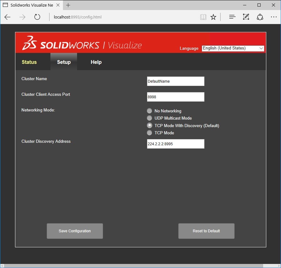
Start Visualize Boost from the icon that should be on the desktop on any machine you wish to cluster with. If you don’t see an icon, start your favorite internet browser and use this address. You should see a screen like this (note: I am using Edge in Win10):
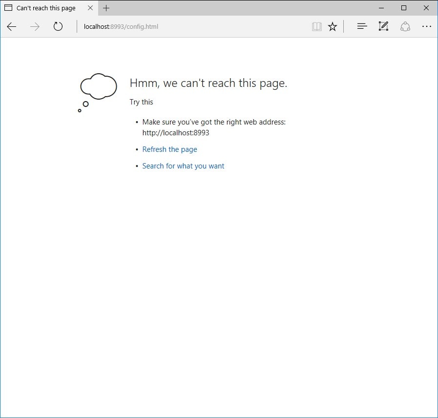
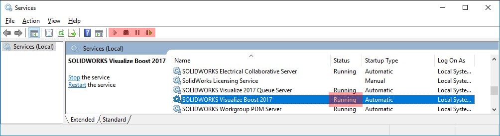
You can also connect to any cluster machine if you know the IP address; just specify the address instead of “localhost” in the address above (ie: http://192.168.0.2:8993/config.html). If when you try to connect and get an error, verify that the service is running. If it’s running, it may be stuck; restart the service. If you don’t see the service, install/reinstall Visualize Boost.
TIP: Start services by searching windows for “services”.
Networking Modes
Now we can start to define the network cluster. There are 3 workable options here, which I will explain below (“No Networking” is only for testing).
UDP Multicast Mode: This mode is best used for LARGE clusters of computers. Large meaning 100’s of machines. Your network needs to support this feature and must be setup on your router before attempting to configure Boost. I have personally never used this mode as our equipment does not support this option. The Cluster discovery address must be a valid Multicast IP address, in the range 224.0.0.0 to 239.255.255.255, and use a port above 1024. The default address is 224.1.1.1:8994. For most users, you should not use this option unless you know your network supports UDP Multicast.
TCP Mode With Discovery: This is the default option, and for most users, should be the one you use. This mode is like UDP mode but uses the more dependable TPC mode of communication. Again, if your network supports Multicast, you can set the Cluster Discovery Address to something like 224.2.2.2:8994, however, Multicast needs to be enabled for you network. If you don’t know if your network supports Multicast, we can use IP addresses instead. Since my network does not support Multicast, I will use this option later to show my setup. This mode is the easiest to setup if your network does not support UDP Multicast mode. If this is the mode for you, skip ahead to My Setup.
TCP Mode: This option is the most difficult to setup because you will need to know the IP address of every machine in the cluster and a single port to communicate with. You should only use this setting if you are using static IP addresses for every machine in the cluster, or if you cannot get TCP Mode with Discovery to work correctly. One machine must be designated the head node. Specify the Cluster Access Port for TCP Mode to be used for the cluster; the default is 8996. Every other machine in the cluster must also be set to TCP Mode (not with discovery) and share the same access port (other client addresses are not needed). On the head node for the cluster, In the Cluster Address List box, input the IP address of each machine and the port to communicate with. For example, you might have 192.168.0.2:8996 (<IP_address>:<TCP_Cluster_Access_Port>) in this list box to connect to one other machine. For multiple machines, use one IP address per line.
Note: you should make a copy of this list, and keep it in a text file to copy and paste back into this box should you need to make changes. Once you apply the settings and close this window, the next time you come back here the list will be empty. I had this option running once, but when IP addresses change, it can be difficult to get running again.
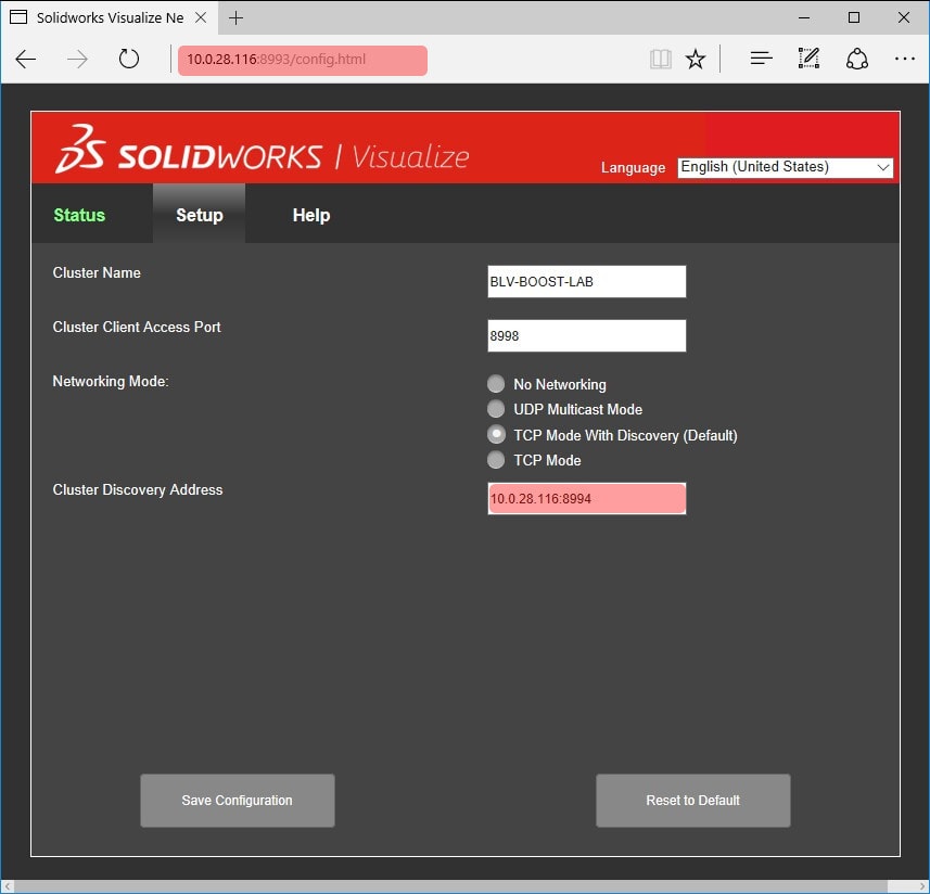
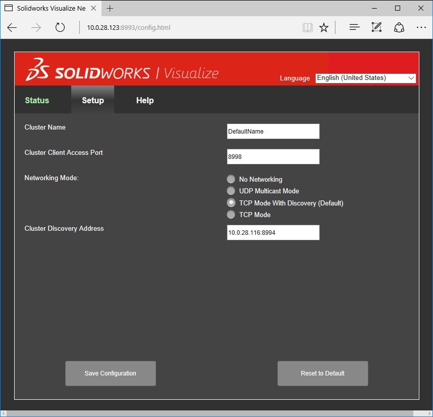
My Setup: Our Bellevue Training Lab has 8 machines, and I will be using TCP Mode With Discovery in this example. Since I know our network does not support multicast, I will designate one machine as the head node and enter its IP address and TCP port I wish to use. I will also give it a Cluster Name to easily see which cluster I’m connected to from within Visualize. Below for the head node, you can see my settings. I have chosen a TCP Port 8994 and have given it a name BLV-BOOST-LAB.
For the rest of the machines in the cluster, I will also use the same settings; however, the name of the server is not relevant since the head node is the only machine I will be using to connect to when using Visualize. Here are the settings for the second machine (NOTE: you could connect and use any machine in the cluster to render with but only the two machines will be used for processing power).
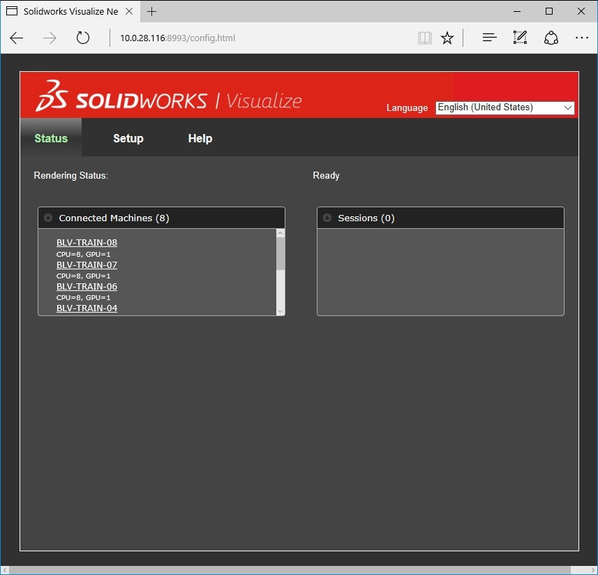
As you enter information into each of the machines in the cluster, you will notice the head node status page updates. The head node will (should) show every computer connected to it in the cluster by name, and how many CPUs and GPUs they are using to render with. Each of the names are hyperlinked and if you click them, will take you to the configuration page for that specific machine. Below you can see I have completed setup of each machine and they all now show in this status page.
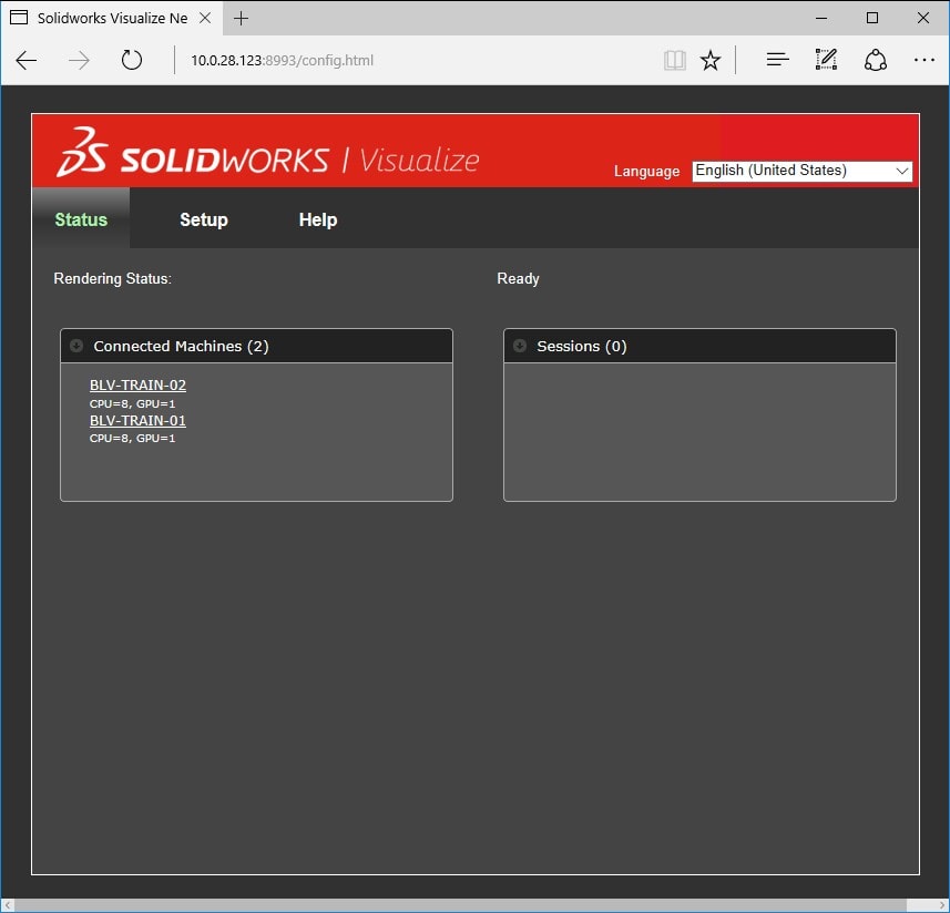
For each of the other machines in the cluster, their status will (should) only show itself and the head node as connected machines (2 connected machines). In the image below, machine 01 is the head node.
Our Boost cluster is now setup and ready to start processing jobs.
Connecting Visualize to the Boost Cluster
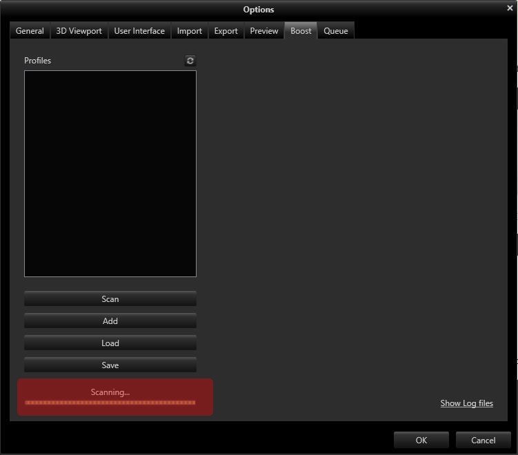
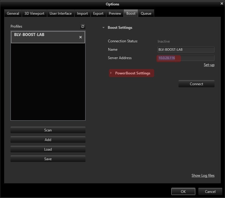
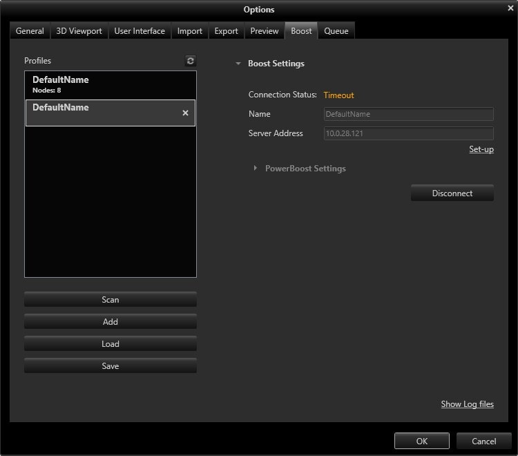
Start Visualize and open a project, then go to tools, options, and then to the boost tab. If you see at the bottom of this window “scanning…” (shown below) you need to open a project, or start a new project before you can change settings. Otherwise, click “Add” to add a new boost cluster (NOTE: Scan will only detect clusters on the current machine or machines on a Multicast Network).
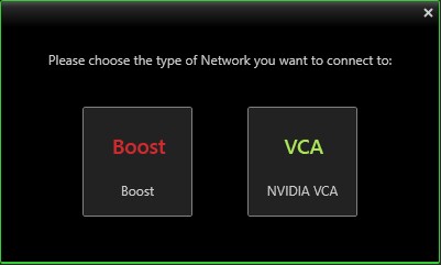
Select which type of network you want to connect to. In this case, I will select Boost.
In the server address box, input the IP address of the head node you defined earlier. As soon as the info is entered you should see the name auto populate in the box as it reads this from the network.
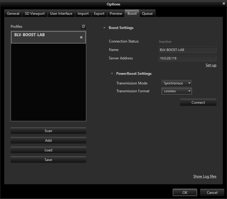
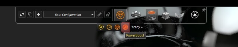
Before we proceed, lets take a moment to look at the other setting by clicking “PowerBoost Settings”.
Transmission Mode has two settings; Streaming (for low bandwidth and high latency like using over a VPN connection on the internet) and Synchronous (for low latency and high bandwidth like a local network). For our network, I will use Synchronous since I’m in the same building as the cluster.
Transmission Format has 4 settings but we should only focus on H.264 (uses very little bandwidth) or lossless (uses more bandwidth, but gives a slightly better image quality). Here I will choose lossless since bandwidth is not a concern.
Streaming Settings: Not used in my setup but important for understanding impact on quality and performance.
Streaming bitrates: Higher values increase image quality but consume more network bandwidth. Lower values save bandwidth but reduce image quality.
Maximum Framerate: Higher values increase image quality but make the application less responsive. Lower values increase responsiveness but reduce image quality.
Latency: Higher values increase image quality but make the software less responsive to user input (such as camera movement). Lower values increase responsiveness but reduce image quality.
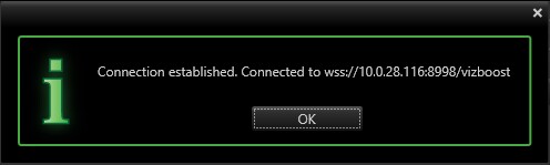
Below are the settings I used for our network. When finished, click “Connect”, you should see a connection established message.
You are now ready to render your project using your new Boost Cluster!
From within the top heads-up display in Visualize, click the option to use boost.
At the bottom of the window, you can see boost working correctly, and the longer you let it sit, the faster it renders. When trying to adjust this image, I was getting about 5 Passes per second, but after letting it sit, it climbs to around 35-45 Passes per second as the cluster sets all the machines to the task of rendering the image.
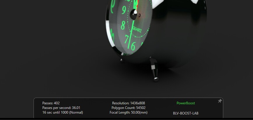
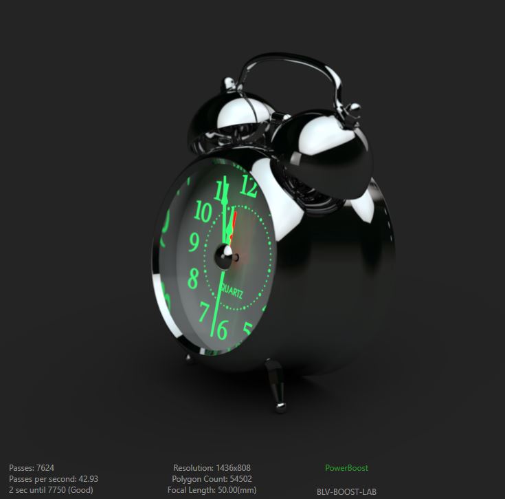
For comparison, my machine by itself renders this project at max 13 Passes per second. For more info on the machines I’m using in this setup go here. Below you can see the progress after about 1 min of letting it process. Now that’s fast!
Troubleshooting: As I mentioned earlier, being able to ping the machines from the computer you want to work from is needed. You also need to have TCP port 8993 open for configuration, as well as two additional ports open for the network; 8998 (or your choice) for clients to communicate to the Cluster, and 8994 (or your choice) for the Head Node to communicate with the other machines in the Cluster. Use PING and TELNET from the command prompt to test.
If things don’t work as expected, first try restarting the “SOLIDWORKS Visualize Boost 2017” (as of this article I am using 2017) service on ALL of the machines in the cluster. The head Node will report the connected machines as the services restart. Don’t forget to restart the service on the head node too.
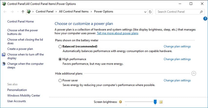
Sometimes you might get a status of “timeout” this might mean that the computer has gone to sleep. Make sure to set all the power settings on the machines to “high performance” to max out the available processor power available for the Boost service, and to prevent the machines from going to sleep.
Boost can be a powerful addition to your workflow and can help save you a LOT of time if you have additional machines not being used on your network.
If you want additional power without the overhead of managing a bunch of individual machines, use an NVIDIA VCA (Visual Compute Appliance) to add a bunch of horsepower all at once.
Alex Worsfold
Application Engineer, CSWP
Computer Aided Technology