Stratasys 3D Printing: Reducing Time and Costs of Composite Tooling with FDM
Reducing Time and Costs of Composite Tooling with FDM
3D Printing your master tooling for a composite layup part can be a great way to reduce time to part and overall costs. Composite tools made with Stratasys’ FDM technology are just as effective and can create parts of the same quality as traditional methods. With traditional manufacturing methods, the time and cost to produce a tool drastically increases with its complexity. However, this is not the case with 3D printing. This introduction to composite tooling with Stratasys FDM will help you decide if FDM is the right process for your needs.
Using FDM for this application is best suited when:
-Cure temperatures are below 350 °F
-Low part volume desired (10s-100s of parts)
-Moderate part size desired (can be built in one piece in a Fortus 900mc or 450mc)
-The geometry of the tool can be adjusted to compensate for tool expansion (due to the tool material’s CTE).
-Desired tolerance is within the achievable accuracy of FDM (+/- .0035in or +/- .0015in/in).
Material Selection
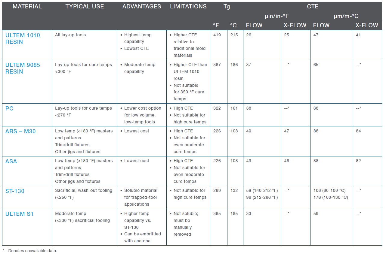
The preferred material for composite tooling is Ultem 1010. It can withstand the highest curing temperature and has the lowest CTE (Coefficient of Thermal Expansion). Other 3D print materials to consider would be Ultem 9085, PC, and ST-130 (a Sacrificial Tooling material). Consult Table 1, below, from Stratasys’ “FDM for Composite Tooling Design Guide” for a best fit material selection.
Table : FDM Material Guidance and General Information
Basic Tooling Considerations
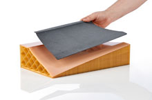
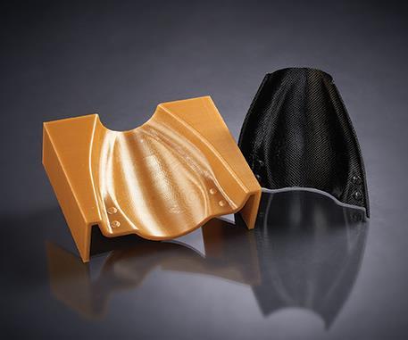
Though most styles of tooling can be utilized with 3D Printing, male molds, or mandrels, are preferred. The printed tool can be sparse filled or shelled in design. A shell style tool will work for most applications and will be the more cost effective option. Due to the slightly higher CTE of FDM Materials, scaling the size of the tool will likely be desired to reach optimal part geometry. Calculating this scaling factor is simple and straight forward:
Tool scaling factor = 1 – [(Curing Temp – Initial Temp) x CTE]
So, if you are curing your Ultem 1010 tool at 300 °F from an initial temperature of 70 °F, the factor is:
Tool scaling factor = 1-[(300-70) x 26 x 10^-6]
= 1- (230 x .000026)
= 1 – .00598
= .99402
For more information on composite tooling with FDM please consult the “FDM for Composite Tooling Design Guide” by Stratasys.
Cody Doiron
Application Engineer
Computer Aided Technology