SOLIDWORKS: Using Construction Lines as Spline Scaffolding in 3D Sketches
Using SOLIDWORKS Construction Lines as Spline Scaffolding in 3D Sketches
Let’s talk about splines.
Not only is spline a fun word to say (try saying it ten times fast), but splines in SOLIDWORKS can be useful for creating curved geometry that cannot be easily described analytically. However, splines can sometimes be difficult to wrangle, especially in 3D sketches. Start adding relations, and they can become downright terrifying. Not so fun anymore.
But there is a solution! You can use construction lines to set up a framework for the general shape of the spline, and to add relations without turning your splines into a can of worms (see what I did there?). In this case study, we will use a construction line to force planar behavior for 3D spline points and to help in adding tangent relations between the spline and other curved geometry within a 3D sketch.
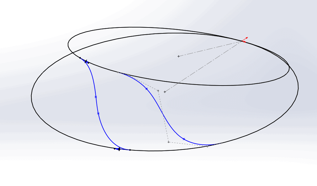
This 3D sketch contains two circles: one sketched on the Front plane and another sketched on a plane (Plane 1) at a 15 degree angle to the Front plane.
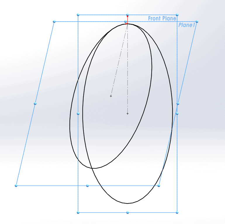
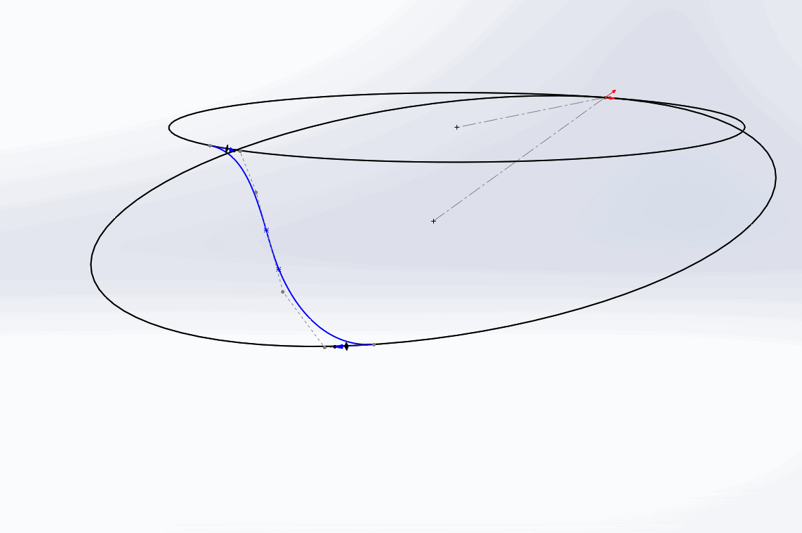
We want to connect these two circles with a smooth spline, which we will eventually use as a sweep path. As such, we would like the spline to be tangent to both circles. Let’s start by simply sketching a four-point spline coincident to both circles.
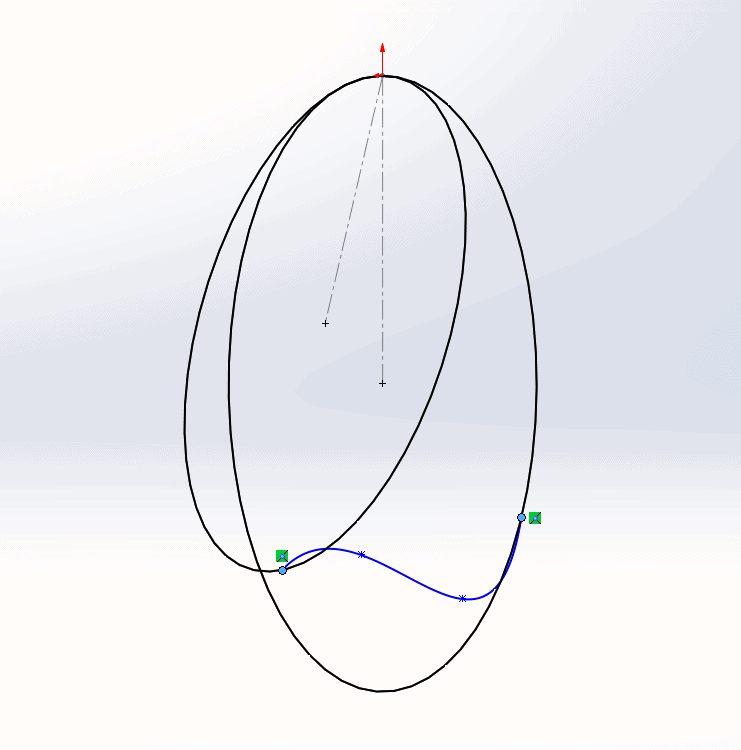
Since we are in a 3D sketch, the spline that we sketch will appear as though it exists on a plane that is parallel to the screen. However, if we rotate the view, we can clearly see that the spline points are actually at somewhat arbitrary locations in space.
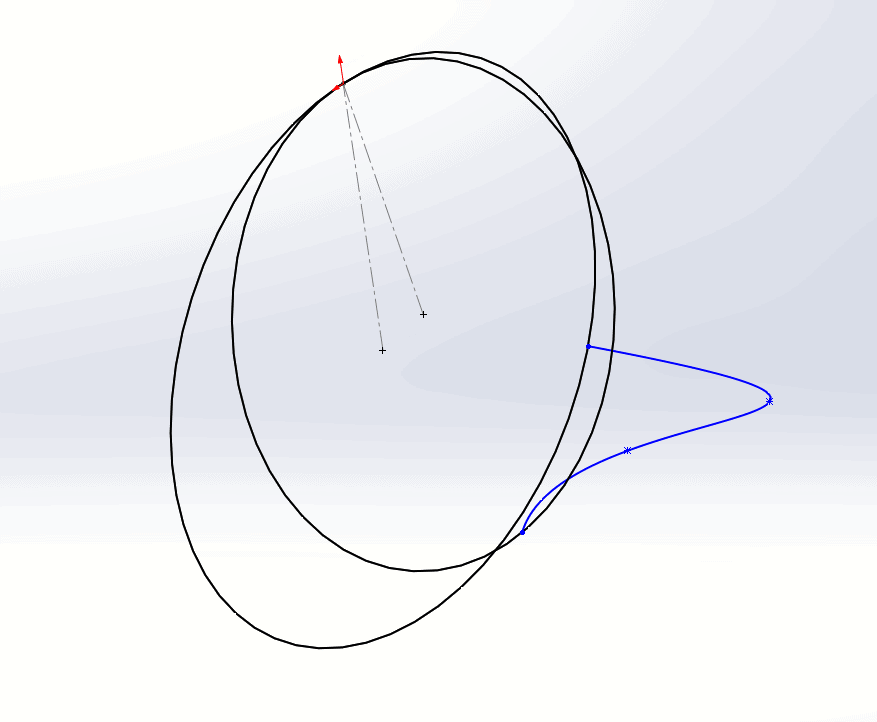
The spline becomes even more unruly if we add tangent relations between it and the circles.
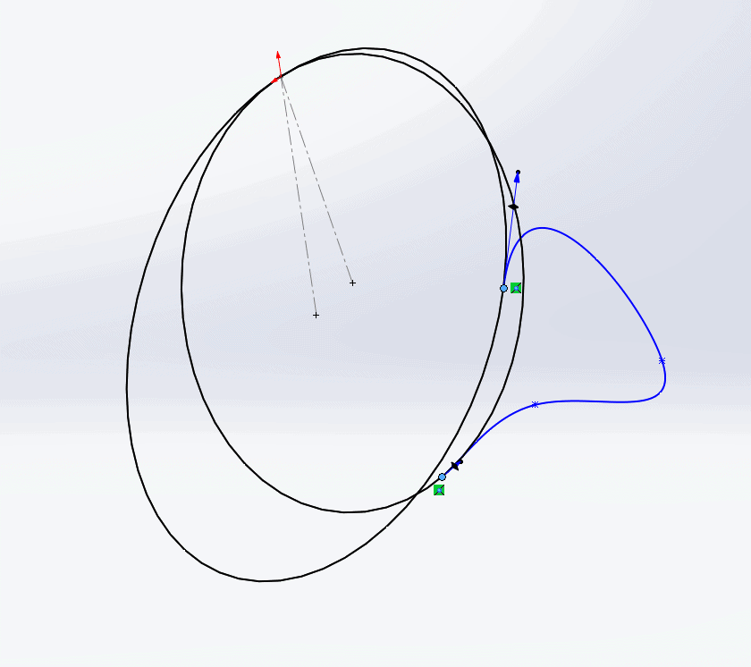
At this point, we have to fight with the spline, using the Handles and Control Polygons from multiple different view orientations in order to wrestle the spline into the shape we need.
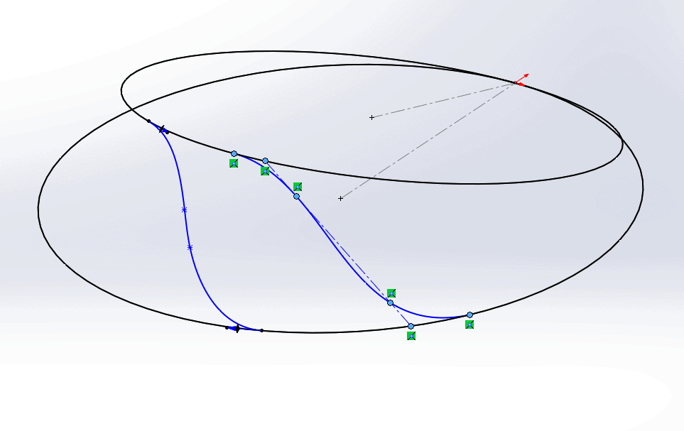
That took way too long. To make our lives easier, we could sketch a construction line that is coincident to the two circles and captures the general positioning of the spline. Then, when we add the spline, we simply make the two interior spline points coincident to the construction line.
This forces the spline points to lie on two planes: one defined by the top spline point and the two interior points (shown in blue in the image below), and the other by the bottom spline points and the two interior points (shown in red).
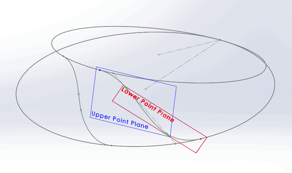
The Upper Point plane was defined by selecting the blue point and the two green points (the two interior spline points) as references. Similarly, the Lower plane was defined by choosing the green points and the red point.
Now, we can and the tangent relations between the spline and the circles without the spline going berserk.
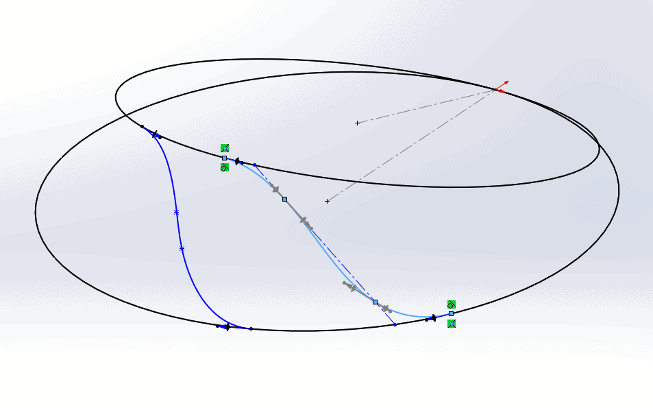
Now, with the tangent relations added, we can delete the centerline and manipulate the spline as necessary to get it closer to the desired shape. The spline will retain its general shape once the line is deleted, so we do not need to worry about rotating the view when adjusting the spline.
So there you have it: spline scaffolding. I’m sure I’m not the first person to use this technique, but I might be the first to give it a sweet name.
Aarya Engineer
Application Engineer
Computer Aided Technology