Stratasys 3D Printing: F123 Series Camera Shroud Print and Install
F123 Series Camera Shroud Print and Install
If you have a F123 series machine and use the camera to view your builds through Grabcad Print software or the mobile app, you will notice in rooms with a fair amount of ambient light that there is a reflection. This stems from the double pane window and the camera being between them.
Stratasys has released a customer level fix for this issue and below are how you go about doing it. First thing you will want to do is make sure you have software version 1.3.5360.0 or newer installed in your printer. You can check this on the machine itself by going to the menu Tools > Maintenance > Update Software and it will show the current version. If you are not at this level, you can then touch the update software on the screen and open Grabcad Print to send the update over through the settings menu.
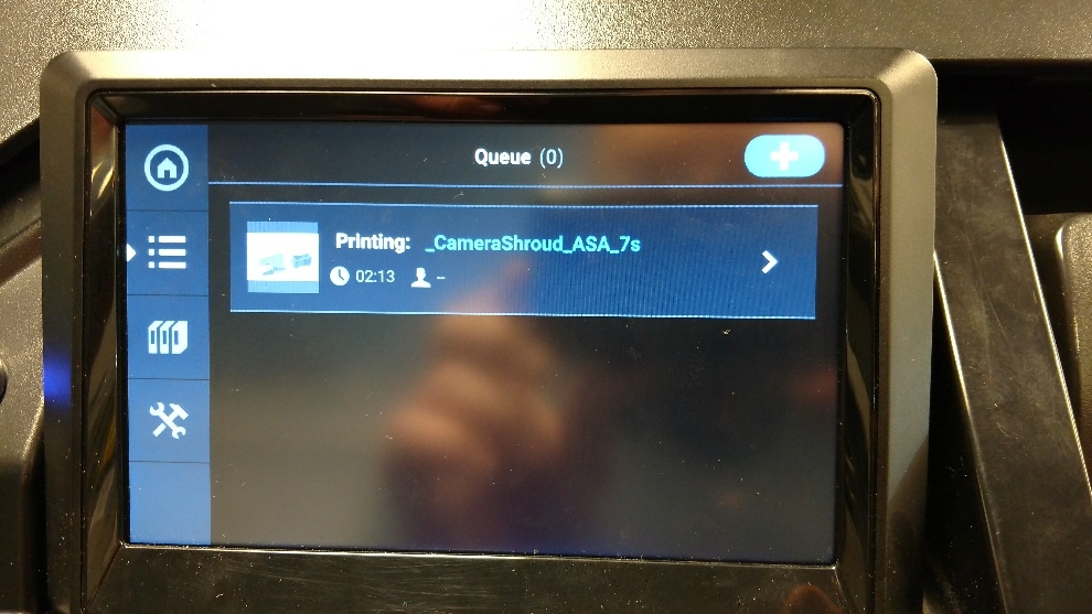
Once you have the new software installed, you can print this new piece right in your printer to use. The file is called _CameraShroud_ASA_7s and though it’s called ASA it can be printed in ASA, ABS, or PC ABS materials. To get the file printed, you will first need to access the print queue through the printers menu, and hit the + sign in the top right corner
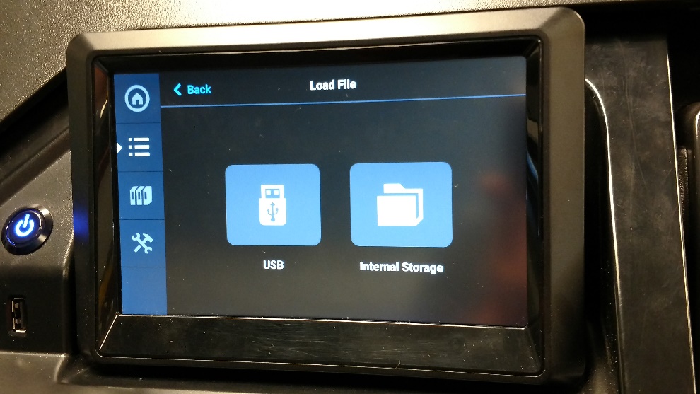
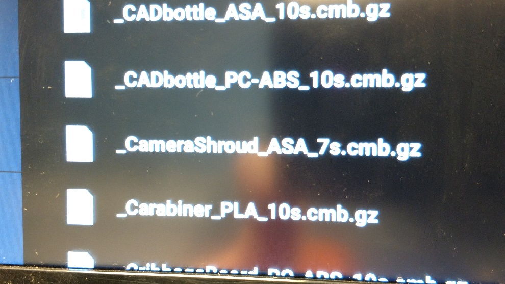
You will then insert the part from the internal storage by scrolling down to the file and selecting it.
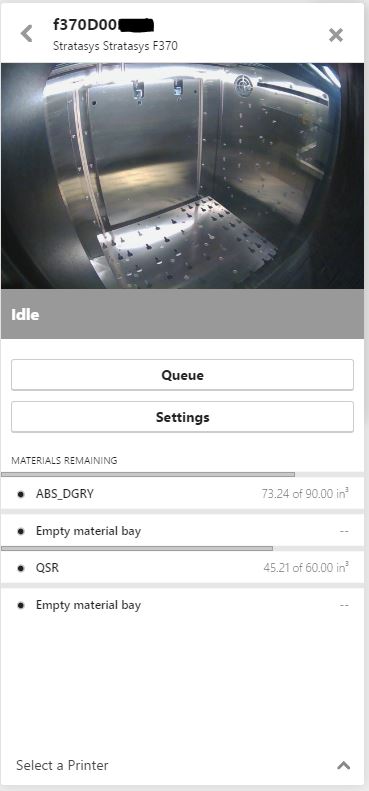
Once it is inserted, if you don’t have ASA loaded but have ABS or PC ABS it will ask if that is ok and to accept that to move forward with the print. You can drag the print around to print wherever you want on the bed surface as well. Once it starts the job, all the info about it will be displayed.
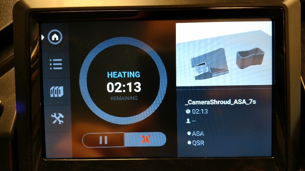
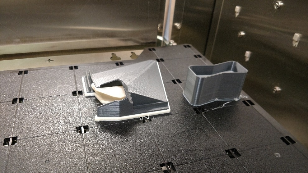
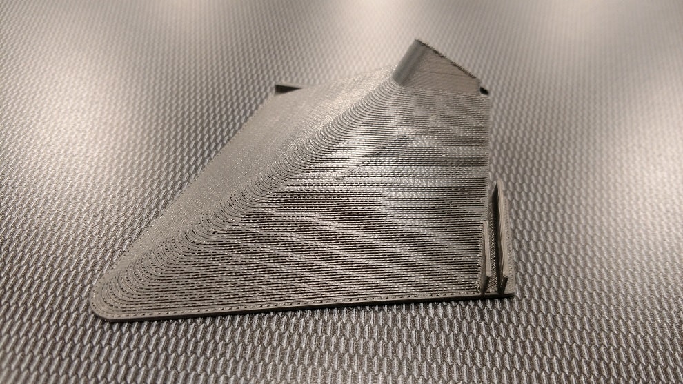
After the 2 hours are up and the part is complete you can remove the tray and soak your part to remove the support. If you are careful with it, it can be removed by hand and in one large piece.
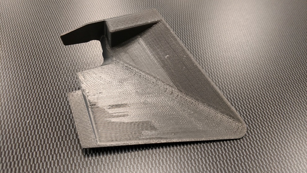
Once your part is out and cleaned up, you can then install it in about 10 minutes. The first step is to open the front door and locate the 11 3mm screws holding the back plate on.
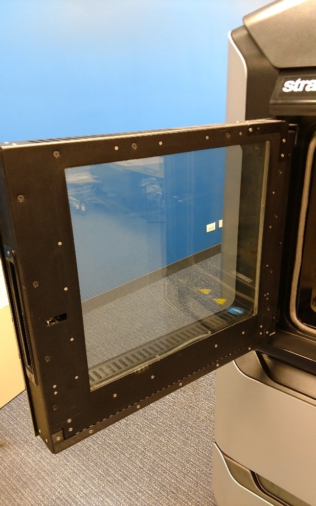
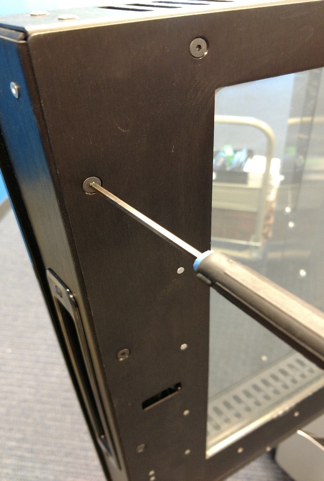
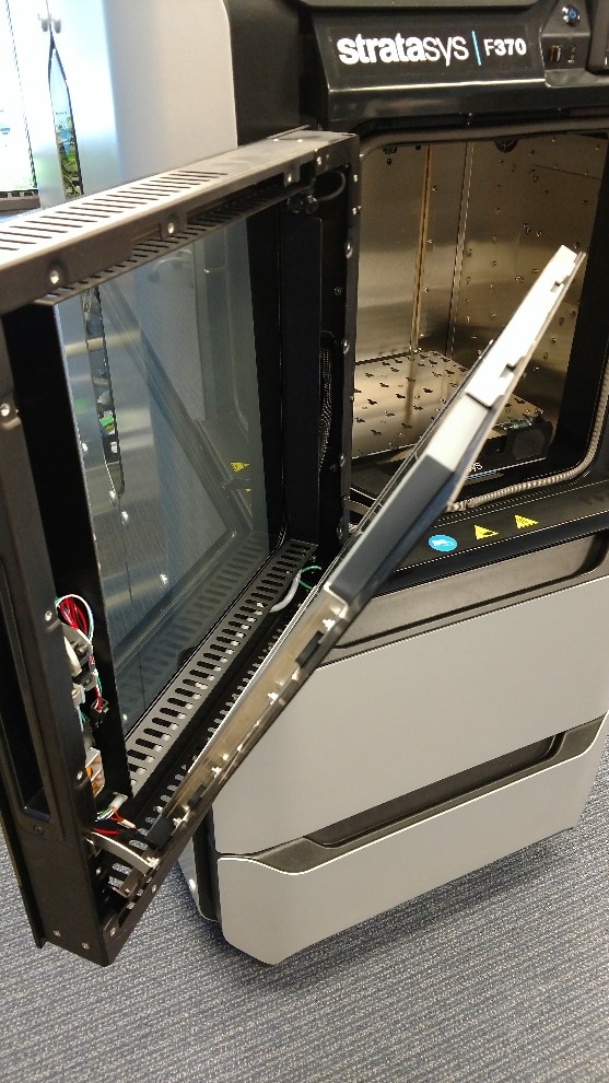
With the screws removed, the back panel will fold in on some hinges and allow you to access the camera.
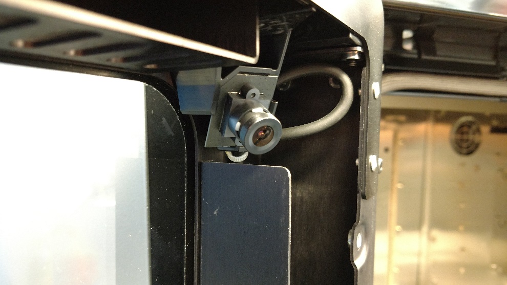
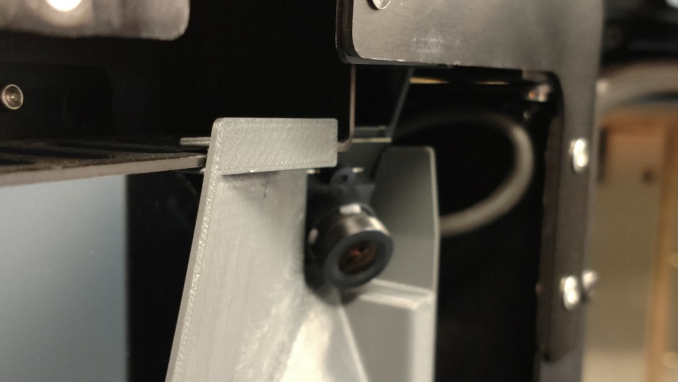
You install the shroud as follows below. It tucks in on the inner edge to the right of the camera and clips onto the upper edge of the sheet metal above the camera. You may have to clip it on and walk it back to the corner to get it fit tighter.
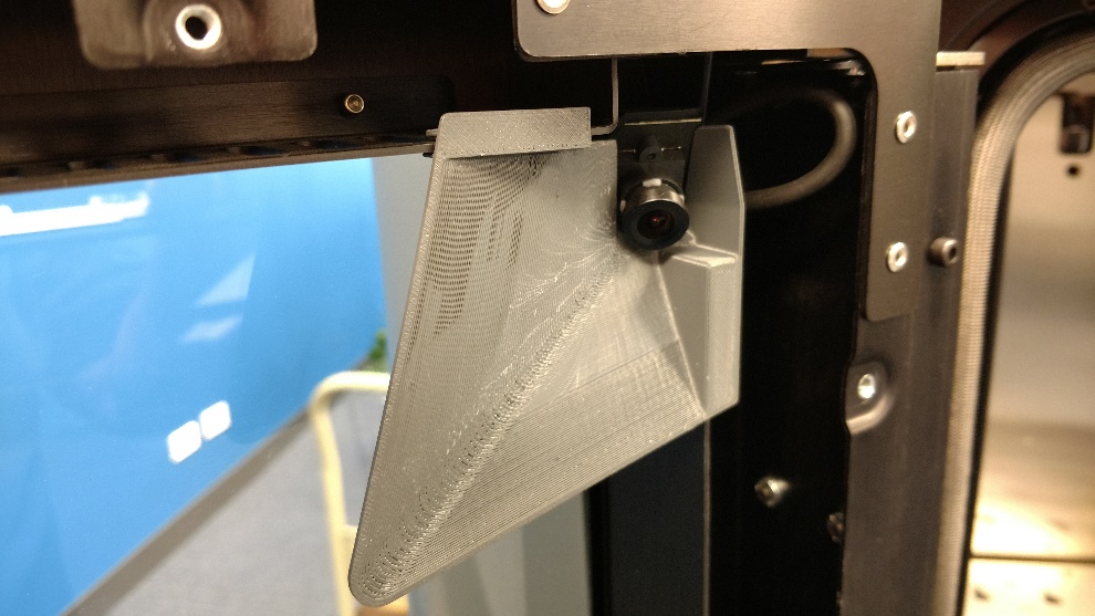
Now is a good time to give the glass a good wipe down as well to make sure its clean and clear for you to see inside the machine. With the shroud installed, you can close up the door and put the 11 screws back in in place.
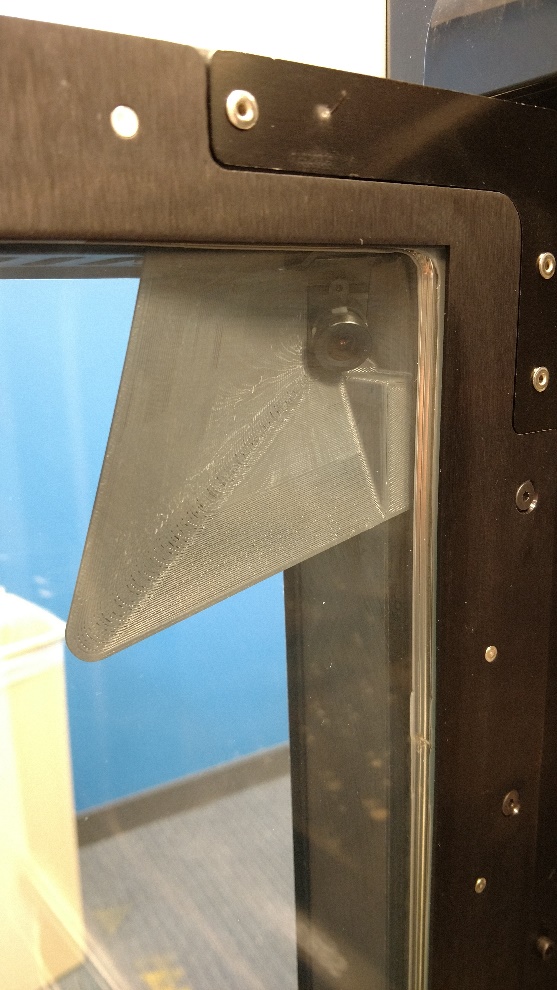
This is how your print area should look now with the new shroud. It is a vast improvement in dark and light rooms for visibility.
Dominick Damato
Field Service Technician
Computer Aided Technology