SOLIDWORKS: Indent Feature
Indent Feature

Among all the features SOLIDWORKS has to offer, the Indent feature is often forgotten. What is it, how do you use it and why would you want to use it? I hope to answer those questions in this blog.
Working with multi-body parts, the Indent feature creates an offset pocket or protrusion on a target body using a tool body or bodies. The contour of the tool body is removed or added to the target part, also allowing a thickness and clearance value to create the feature. The Indent feature can be used with solid and surface bodies. The Indent feature is different than the Deform Feature because the number of faces, edges and vertices remain unchanged in the final body whereas the Indent feature will change the target body.
Requirements for the Indent Command
- Either the target body or the tool body must be a solid
- To indent, the target body must be in contact with the tool body, or the clearance value must allow for a protrusion through the target body.
- To cut, the target and tool bodies do not have to be in contact with each intersection with the target body.
- To indent (cut) a solid with a surface tool body, the surface must completely intersect the solid.
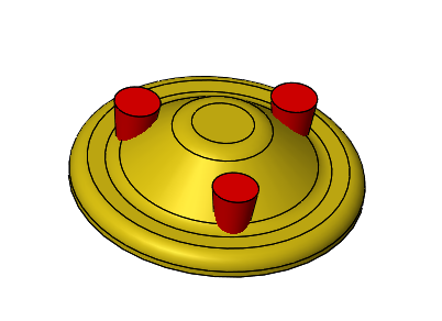
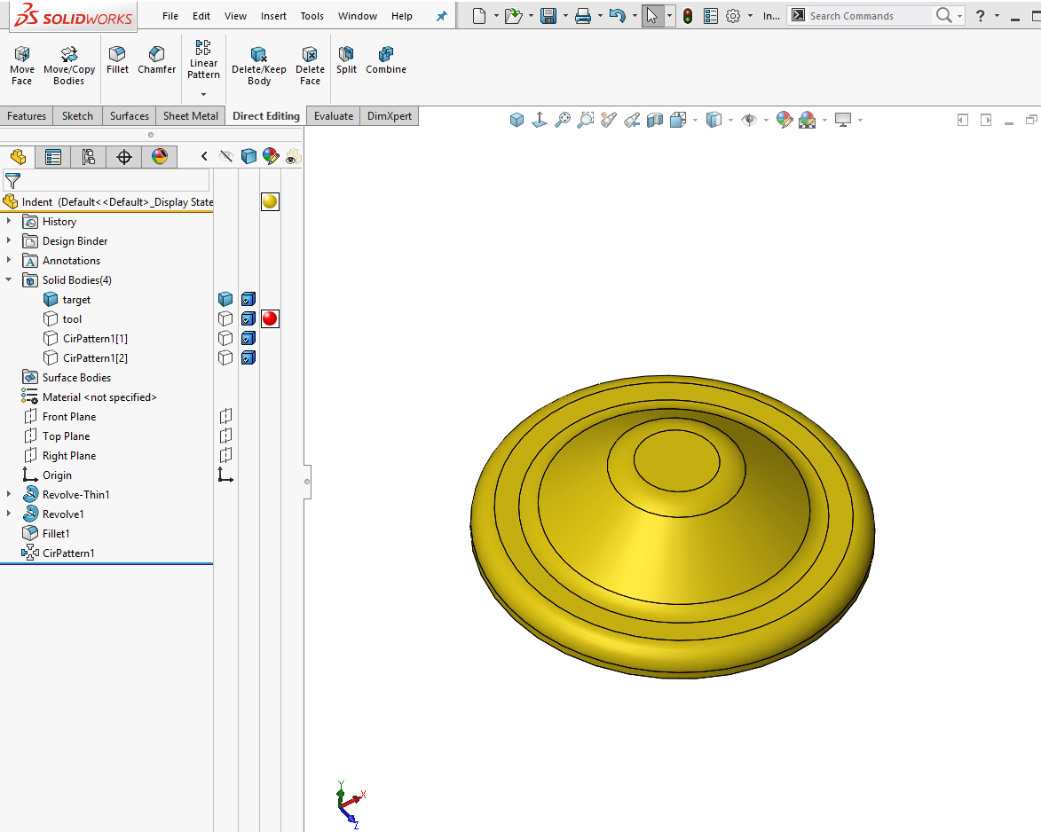
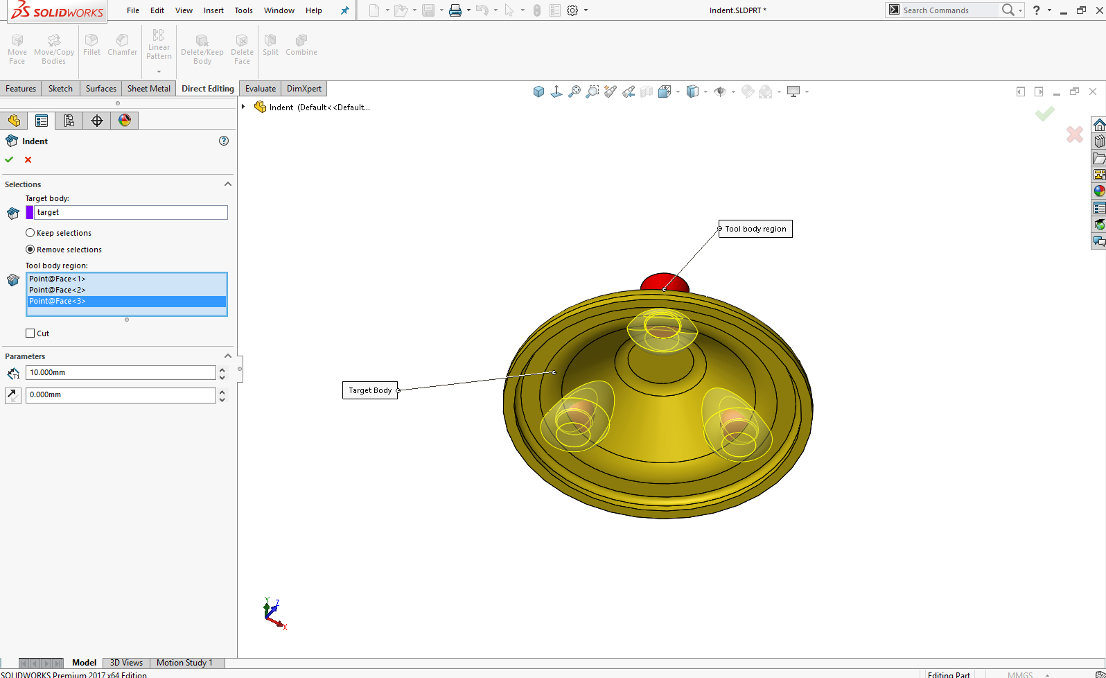
In this model, we have a Target body (yellow) and 3 Tool Bodies (red):
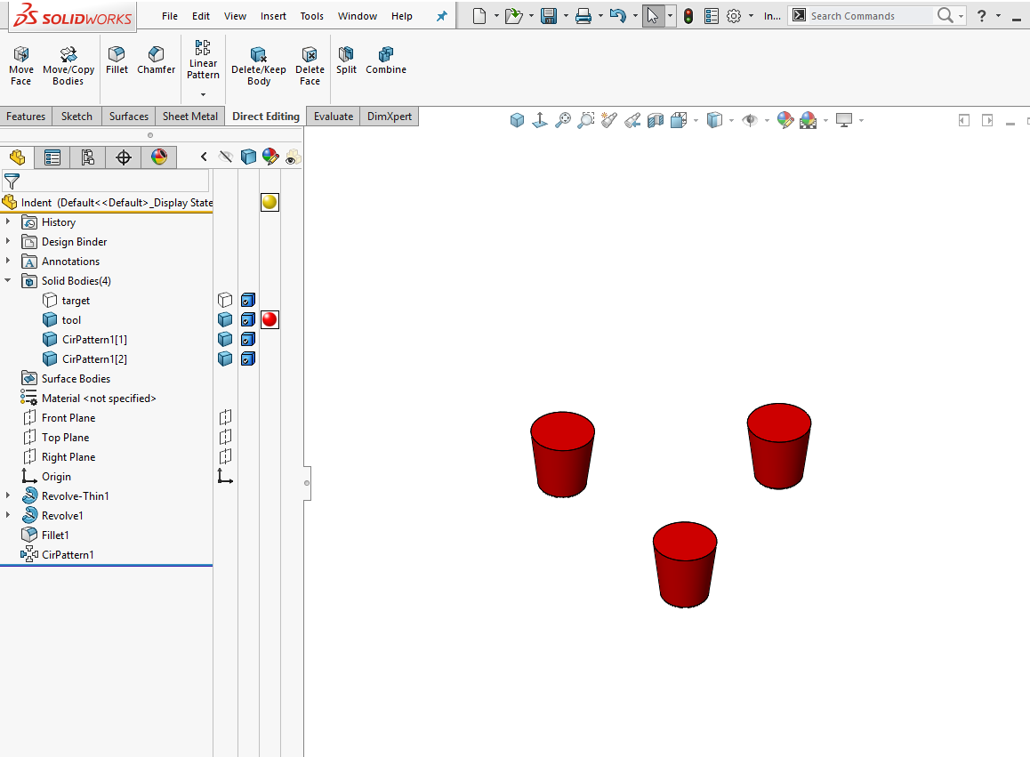
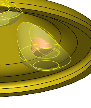
By hiding solid bodies, we can see the individual bodies.
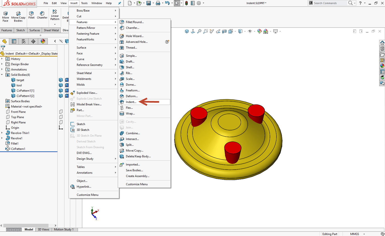
By using the indent feature, we will take the 3 tool bodies (red) and indent the target body (yellow). When using the Indent feature, we will have a few options of how we want our indent to look. Let’s begin.
Go to the menu bar and select Insert > Features > Indent.
The Property Manager shown wants to know the Target body and the Tool body regions.
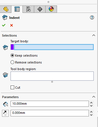
To create an Indent feature
- Select a solid or surface body for the Target body.
- Select one or more solid or surface bodies in the graphics area for Tool body region.
- Choose the side of the model to keep by choosing Keep Selections or Remove Selections. (These options invert the side of the target body to indent).
- Select the Cut checkbox to remove the intersection are of the Target Body.
Under Parameters
- Set Thickness: (for solids only) to determine the thickness of the indent feature.
- Set Clearance: to determine the clearance between the target and tool bodies. Click Reverse Direction if needed.
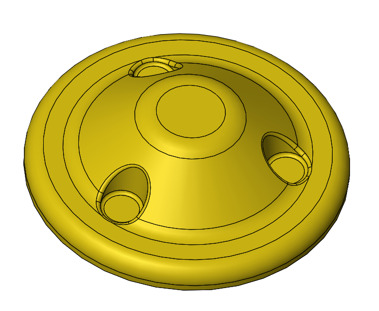
Here is an example of creating a 10mm wall around the tool body.
When you click OK 
this is the final product:
I hope you found this helpful.
Thanks for reading!!
Judy Marlo. CSWP
Application Engineer
Computer Aided Technology