SOLIDWORKS: Time to FLEX Your Modeling Skills
Time to FLEX Your SOLIDWORKS Modeling Skills
I wanted to take the time to introduce to you a rarely used but incredibly powerful weapon in the SOLIDWORKS arsenal. With the FLEX feature at your disposal you will be able to transform your solids into fantastic shapes, only limited by your imagination.
I will walk through the basics of the FLEX command and show you how it will deform even complex solids in an intuitive manner.
There are four types of flexes:
- Bending
- Twisting
- Tapering
- Stretching
I will demonstrate each of these types and the result will be a solid that would challenge any experienced SOLIDWORKS modeler.
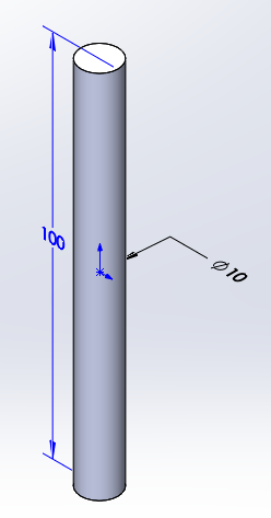
I will begin with a simple circular extrude to create a solid 10mm DIA X 100mm long.
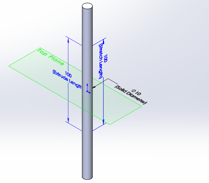
I will then begin to deform the solid using the FLEX feature to add 100 mm to the length by stretching.
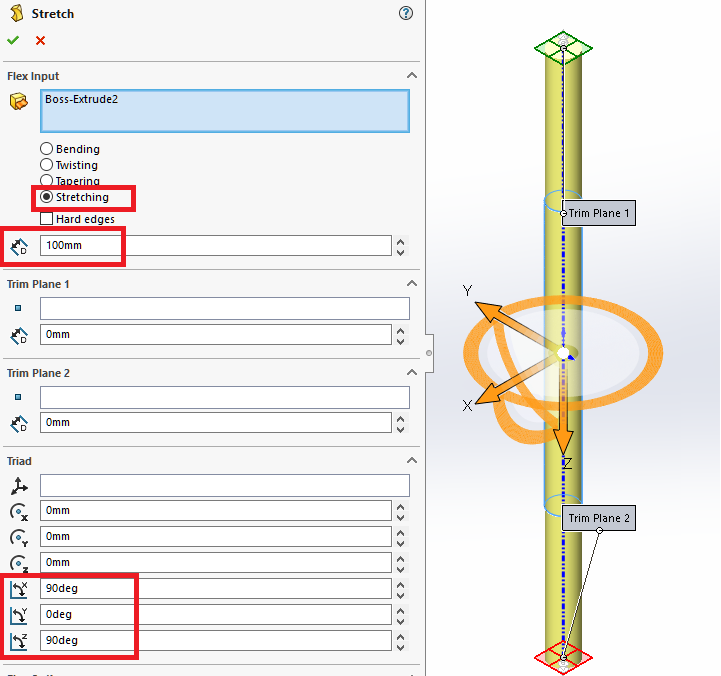
Start the FLEX feature and select Stretching, the add 100mm and set the axis as shown, SOLIDWORKS automatically places the trim planes at the boundaries of the solid and by leaving the triad at the center of the part 100mm will be added symmetrically to the length of the solid, keeping the Top Plane at the center of the solid.
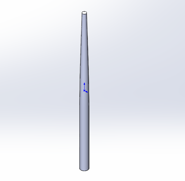
Next, I will apply another FLEX feature to Taper the top of the solid by 50%
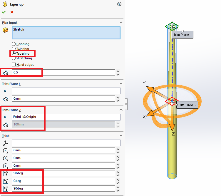
Select Tapering, then set the effect to .5 and set Trim Plane 2 at the origin, with the axes set the same as previously, only the top half of the solid is the effected.
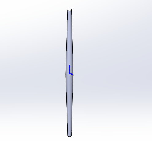
Apply another FLEX feature to Taper the lower half of the solid.
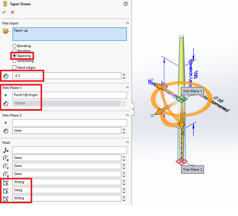
This is accomplished with the same Tapering selection, input -.5 then set Trim Plane 1 to the origin with the previously set axes.
Notice that the solid is still symmetric about the origin. This will be important as I develop the solid.
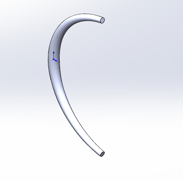
Now the FLEX Feature will be applied again to Bend the solid.
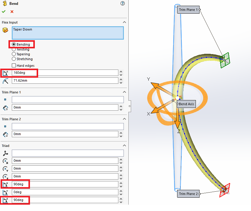
This is done by selecting Bending and applying a 160-degree bend with the previously set axes. NOTE: The 71.62mm setting is disregarded at this time.
The next objective is to create a circular pattern of this solid.
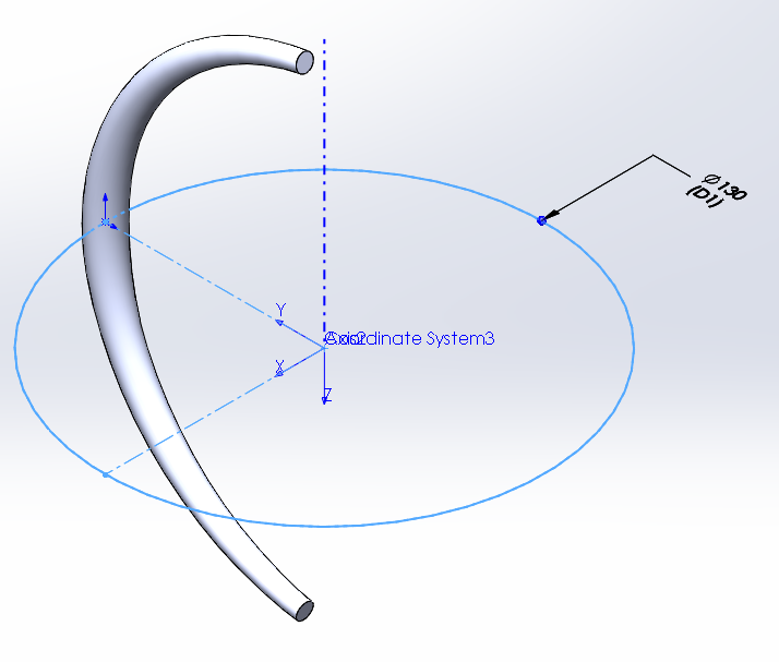
To facilitate the circular pattern, I will create a sketch on the Top Plane and add a circle with the circumference at the origin and the diameter set to 130mm. From that I will add an Axis and set a Coordinate system to the same axes as we had used previously.
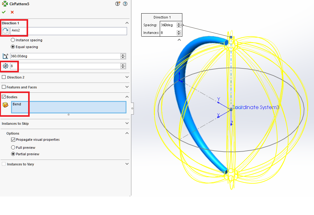
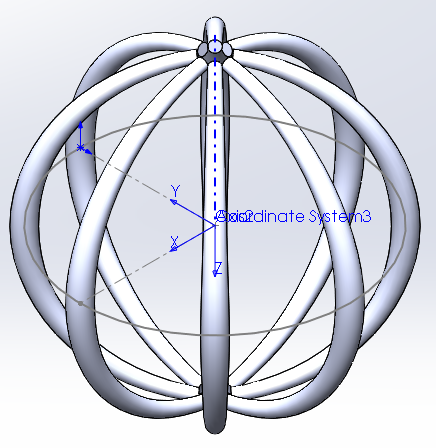
Using the axis create a Circular pattern of bodies with 8 instances.
Now I will us the FLEX feature again to apply a Twist to these solids.
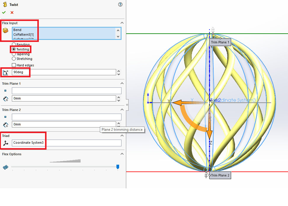
This is done by selecting all the solids, then set to Twisting, with a 90-degree input. By having the Coordinate system set previously the selection is simplified.
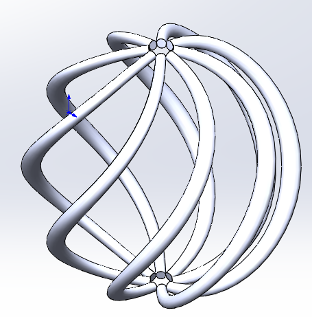
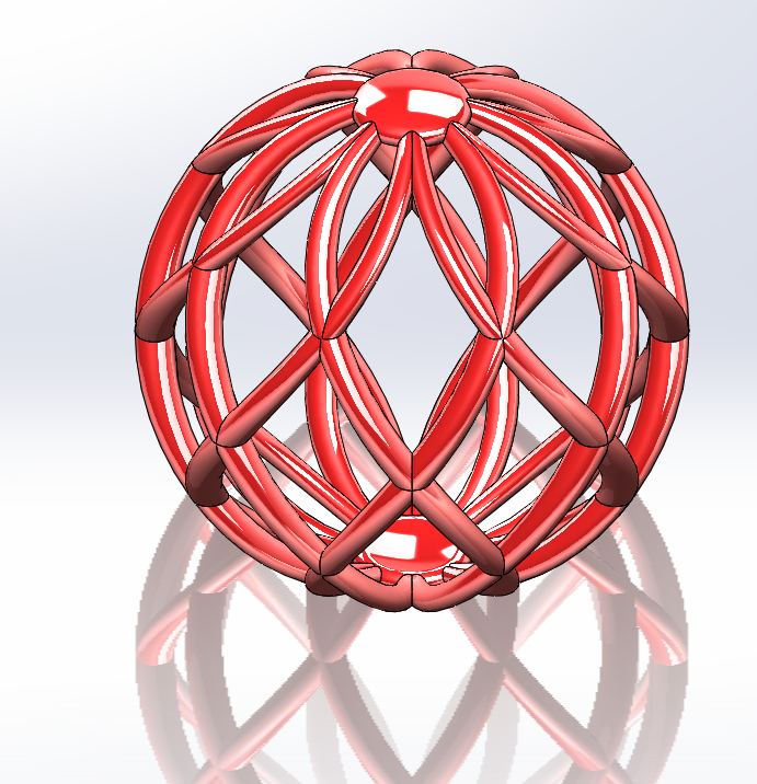
To add more interest to this model I will mirror these bodies across the Top Plane and using the merge entities option there will eight solids after the Mirror feature.
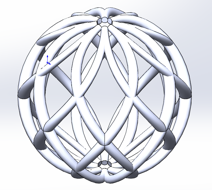
By adding a simple revolve feature at the top and mirroring it to the bottom all of the solids will be merged and the model is finished.
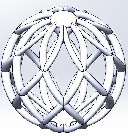
If you add an interesting appearance and turn on RealView Graphics this model will appear more dramatic.
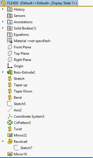
And finally, here is what the Feature Manager Tree looks like when finished.
I hope you have enjoyed this trip through the FLEX feature and will have an opportunity to use it with future designs.
Dennis Barnes
Application Engineer
Computer Aided Technology