Forgotten SOLIDWORKS Tools and Reasons to Use Them
Within SOLIDWORKS, there are some useful tools and features that many users overlook or simply forget about during their daily grind. In this blog, I’ll be discussing one of my favorite additions to the software that is often forgotten about: SOLIDWORKS Up to Reference Patterns.
The SOLIDWORKS Up to Reference Patterns tool allow the user to create patterns that are driven by the geometry of their part. Conditions can be set for the spacing, number of instances, but references for where the instances are measured from as well as where they end. Up to Reference Patterns allow the user to create dynamic patterns that change with the size parameters of their part geometry. Keep reading to learn more about this useful tool and why you should start using it now.
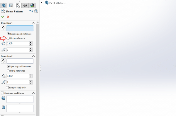
Up to Reference Patterns can be found as an option in the linear pattern property manager shown by the red arrow below.
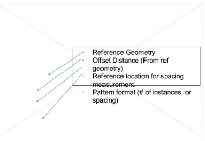
Once selecting the option “Up to Reference” we can see a very different set of options. Notice how we can now choose reference geometry, an offset distance from that geometry, a spacing measurement reference for the feature that we’re patterning, as well as the choice to choose instance spacing or the number instances needed.
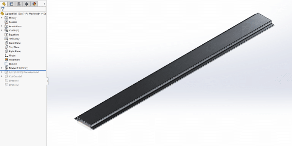
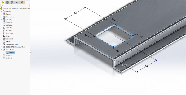
I’m going to keep it simple, and work with a simple structural member that we’ll add some features to. The part I’m working with is a support rail that will have other parts bolted to it.
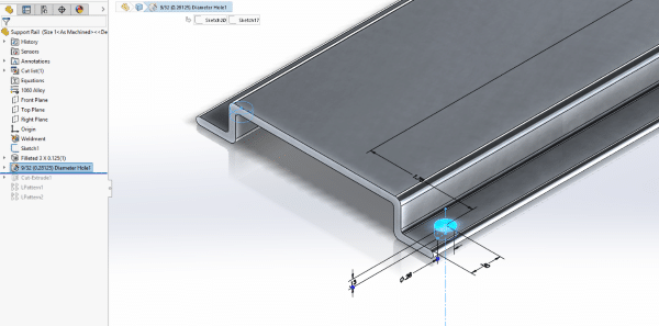
Before we send this structural member out for production, I want to add some cuts and holes to it. I’ll use the planar faces of the extruded piece to create my sketches for the features.
With the features added, I’ll get to applying my pattern, but let’s throw a curveball in here. Let’s say that I want to make a set of configurations of this particular part. In this particular part I want to have three configurations for use. I’m not worried about the number of features, but I do have specific lengths that my customer is requiring. Up to Reference Patterns allow my features to be replicated dynamically pertaining to the parameters of my part.
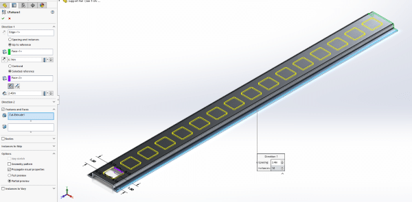
Once I’ve created the seeds for my first two features, I’ll go to “Linear Pattern” to start setting the criteria. I’ll start by choosing a direction for the pattern, followed by the feature that I want to pattern. Immediately I see a preview of the pattern to be created for the cut feature I selected.
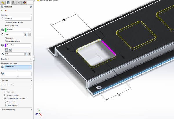
If I was applying a regular linear pattern, I would set my spacing and be done, but there a couple of other steps needed for an Up to Reference Pattern. First I’ll choose the reference geometry, this tells the software where I want the pattern to terminate. I’ll choose the opposite end face where the rail is cut.
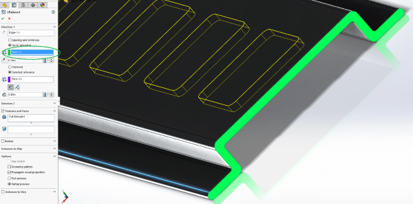
This face is highlighted and placed in the “Reference Geometry” selection box. The selected face now acts as a terminating plane for any instances of the seed being patterned. This means if an instance of a seed runs over the plane of the selected face, it will automatically be deleted. So the geometry is governing how many instances of the square cut in on the rail. I also have the ability to set an offset distance from the reference geometry so that I don’t have any features too close to the end of my part.
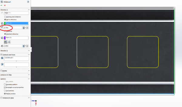
SOLIDWORKS allows me to choose the reference location from where I want the software to measure my spacing. I can choose Centroid (length/width mean) or a selected reference. I’ll choose the inside face of the square cut to measure my spacing from. Now the software will start measuring from that face to place each instance.
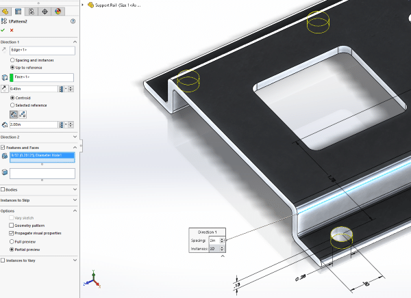
I can now click the green check and run through the same steps to pattern my hole wizard feature. Selecting the direction of the pattern, the Up to Reference geometry, the feature to pattern, and the offset distance if desired.
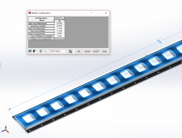
After clicking the green check, we have the patterns that we need, and can now move to configuring the part. By choosing the length parameter and right clicking, I can choose “Configure Feature” to create new configurations and add different lengths to each configuration. This allows me to have multiple variations of the part in the same file.
Once my configurations are complete, I can place my part in a drawing and begin to break out my views for production.
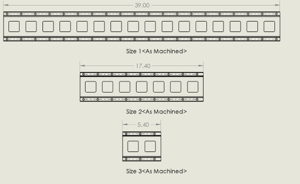
Previous to having the Up to Reference pattern, the user would need to write two equations to produce a similar result. Up to Reference saves time, and allows you one less thing to think about when creating configurations of your finished parts.
I hope you found this SOLIDWORKS tip helpful. You can view more SOLIDWORKS tips and tricks listed below.
More Tips & Tricks
Where is the SOLIDWORKS Command That Lets Me Do…
How to Utilize the SOLIDWORKS Customer Portal
Don’t forget to subscribe
About the Author
 Jay-Shan Jackson has been with the Fisher Unitech family since 2017 as a Customer Support Engineer and is based out of the Fisher Unitech office in Cincinnati, Ohio. Jay-Shan is a Certified SOLIDWORKS Expert with an expertise in mechanical design.