Weld Analysis in SOLIDWORKS Simulation: Connector Series
I have been asked a lot lately about how SOLIDWORKS Simulation can help with weld analysis. Welding is a crucial joining method in many designs. However, the actual welding process is quite complex as is the resulting material microstructure. The heat affected zones (HAZ) in welds are a big consideration, and SOLIDWORKS wrote a very good blog about approximating weld distortion due to the HAZ. In this blog, we are going to ignore that microstructure phenomenon and focus more on a much simpler way to size and analyze welds: The Edge Weld Connector.
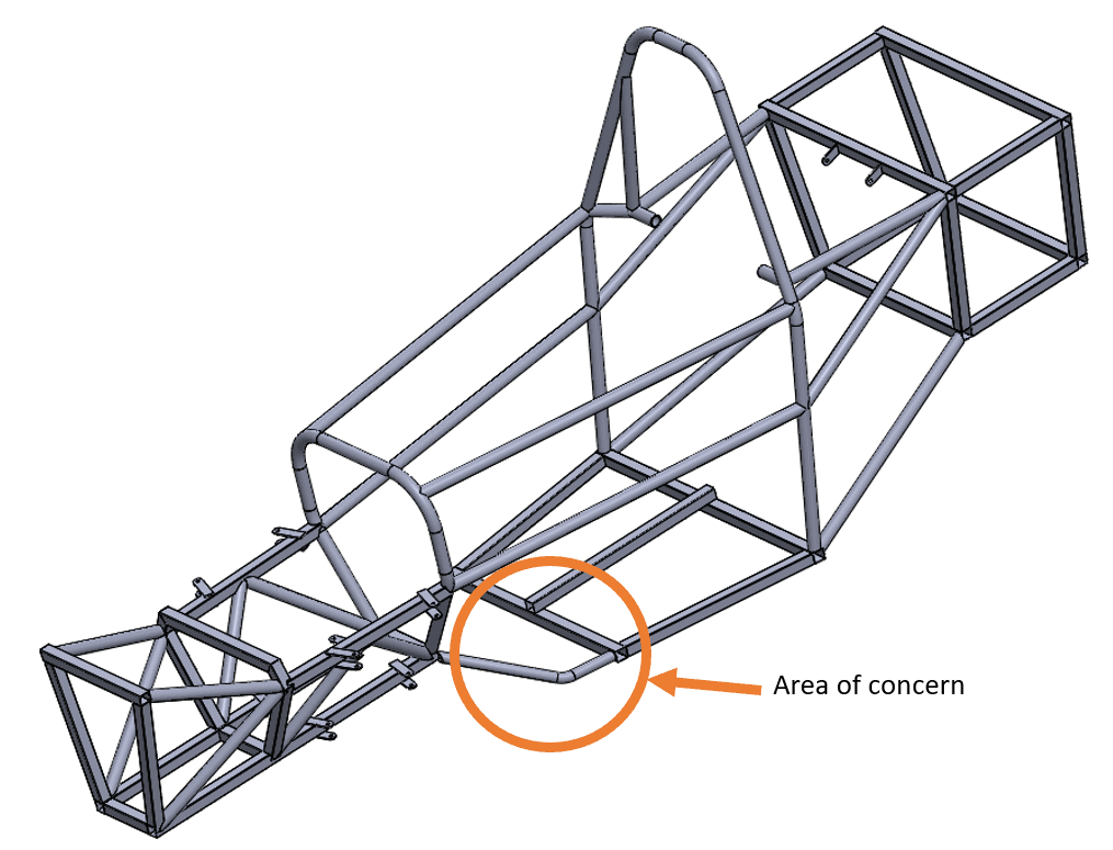
The Edge Weld Connector is included in SOLIDWORKS Simulation Professional and SOLIDWORKS Simulation Premium. The purpose of the Edge Weld connector is to give the engineer a way to validate sizes and types of welds for their designs without having to do coupled thermal-structural analyses. For this blog, I am going to use a custom car frame and look at one area to demonstrate how the edge weld functionality works. To keep things simple enough for a blog I will be analyzing just one part of the structure.
For the Edge Weld connection to work, there are a few criteria we need to meet.
- For a butt weld (fillet weld), the welded edge of the first component must be completely terminated by the face of the second component.
- For a fillet weld, the two components must be perpendicular.
- At least one of the bodies involved in the weld must be comprised of shell elements.
With those criteria met, the actual setup of the weld connector is quite simple. You have 4 choices in the weld definition: fillet weld or groove weld, and each can be single or double-sided. Select the two faces involved in the weld, and then the edge that lies at their intersection.
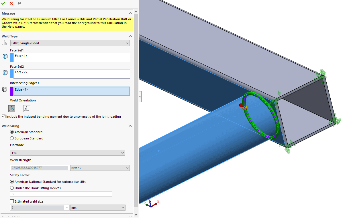
Once the weld is defined, the user can then choose which side the weld is on (if applicable), and the weld standard. SOLIDWORKS Simulation uses two well-known weld standards. The American Standard from American Welding Standard D1.1 & 1.2. These cover steel and aluminum welding standards respectively. The second standard is the European Standard according to Eurocode 3. Once the applicable standard and inputs are entered, you have the choice of defining your own estimated weld size or to allow the software to estimate one for you.
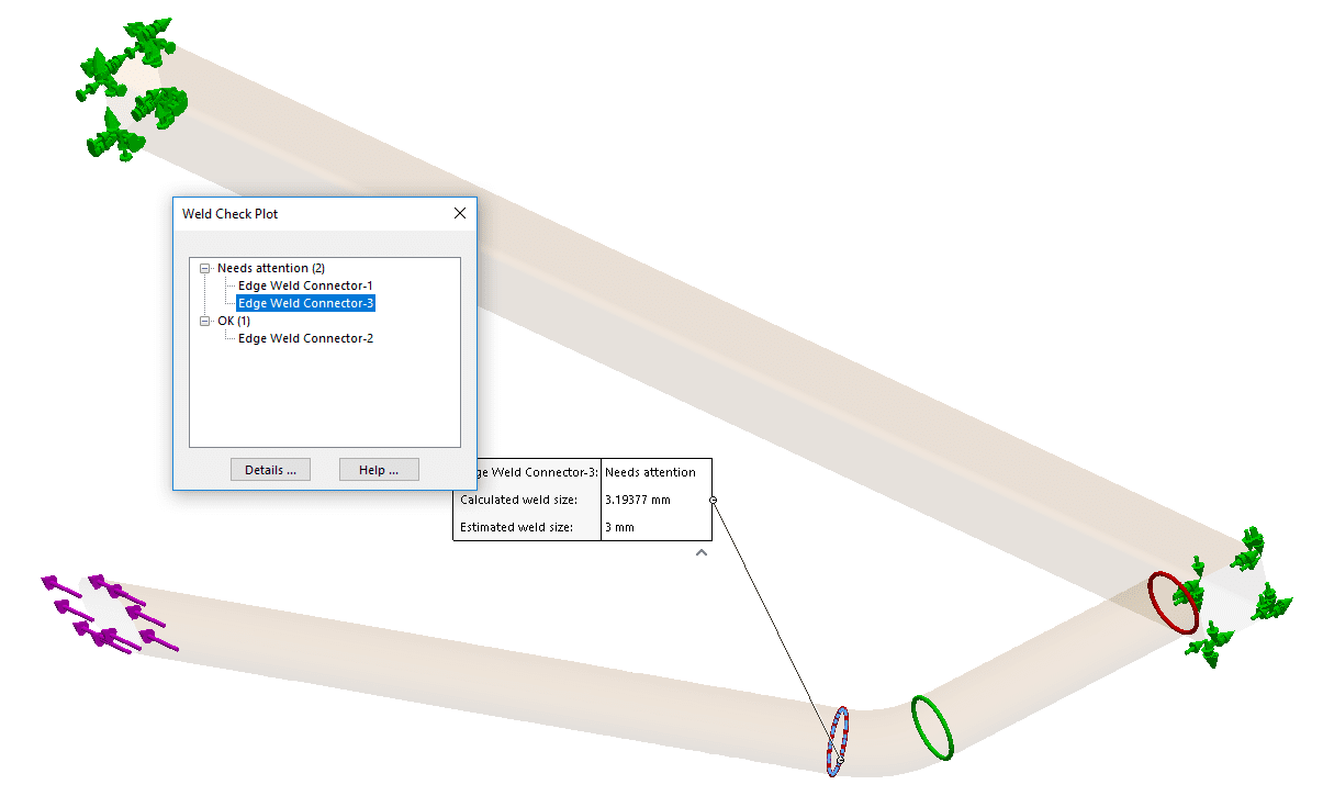
In my model, I applied one edge weld and two groove welds to the structure, as seen below.
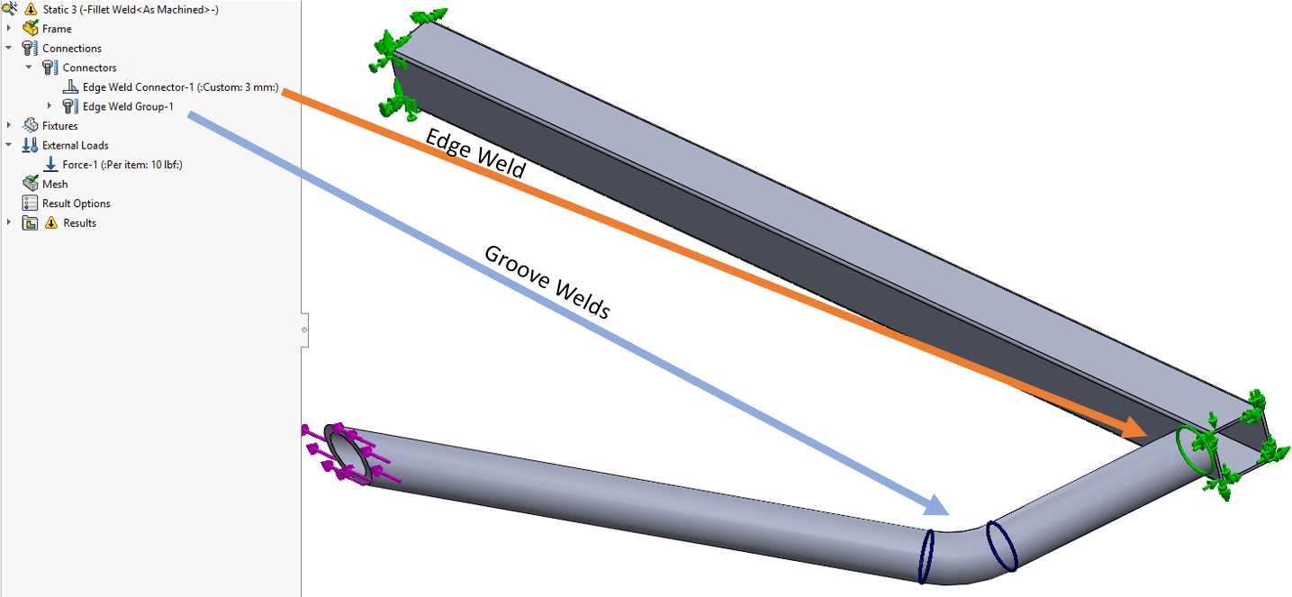
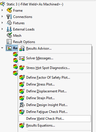
Notice these welds are the only connections or contacts in my simulation. After the rest of the setup is complete, we can view the results. To gain insight into the strength of our welds, simply right click the results folder and Define Weld Check Plot.
The plot shows any and all welds in the simulation and organizes them into “Ok” and “Needs attention” categories in the dialogue box. In our case, there are two welds that need attention; i.e. there are two welds that have a calculated weld size that is greater than our initial estimate. By highlighting any of these, you can get more information.
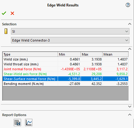
You can also extract more comprehensive data about these welds by clicking details. This will display an Edge Weld Results manager that will display the range of weld sizes calculated, their joint normal force, shear force from the weld axis, shear force from the weld surface normal, and bending moment. This type of data is invaluable to weldment designers and is easily extracted from edge weld connections. In the case of our analysis, I must resize some of the welds so that they do not fail according to our standard.
In this blog, we discussed the edge weld connector included in SOLIDWORKS Simulation Professional and Premium. There are many types of connectors in SOLIDWORKS Simulation all of which have the end goal of making simulation simpler to use and obtain more robust results. For more about SOLIDWORKS Simulation or other SOLIDWORKS tips and tricks, reach out to your local CATI representative today!
Matt Sherak
Applications Engineer, Simulation
Computer Aided Technology, LLC