Insert Molding with SOLIDWORKS Plastics
What is the correct term – insert molding or insert overmolding? I hear the terms used almost interchangeably in conversations about SOLIDWORKS Plastics. I always ask the speaker for clarification. The ask is not because I do not understand what both terms mean, I want to make sure that we are discussing the same thing. Let’s clarify the terms so we can move forward with today’s blog. Insert molding is the process of adding an insert, typically a metal component, into the injection mold tool prior to filling the cavity with molten resin. This process encapsulates the insert and can produce a stronger, more durable finished product than an assembly requiring multiple secondary operations like machining and gluing. Overmolding is the process of injecting multiple resins into the mold tool, one after the other, to create a multi-material product. Overmolding is often encountered on parts where a rigid base component is needed for structural function and a soft outer layer is desired for tactile function. For this blog, I will focus on insert molding and how threaded inserts can be included in a SOLIDWORKS Plastics study.
Insert molding analysis is possible with SOLIDWORKS Plastics Professional and SOLIDWORKS Plastics Premium. You will need a multibody part file with individual volumes for the cavity and each insert. For the best results, make certain that the touching faces between the cavity and insert(s) are identical. Including inserts in the SOLIDWORKS Plastics study requires a solid mesh for the analysis (Figure 1).
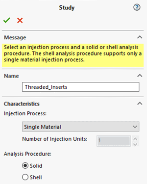
Figure 1.
Setting up the Study
Once the study is created, the SOLIDWORKS Plastics feature tree will look similar to Figure 2. The setup begins with defining the properties of the injection unit, then assigning the correct domains to each body for the cavity and the insert(s). When assigning the insert domain, you must specify the material for the insert. Similar to when assigning a plastic resin to the injection unit, you will see any recently used materials for inserts in the list.
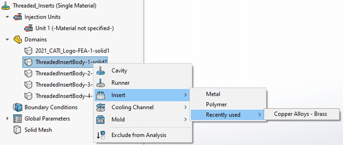
Figure 2.
Next, assign properties to the inserts, specifically the temperature of the insert when placed into the injection mold tool. This boundary condition can be added to multiple inserts in one step if you use shift-select prior the right-mouse button to access the insert properties (Figure 3). This step should not be overlooked as it will affect the Fill results, especially near the cavity-insert boundaries. The inserts will often be at room temperature which can be significantly lower than the operating temperature of the injection mold tool. This can cause portions the plastic melt front to freeze upon contacting the insert, inhibiting the Fill process. This can be visualized when post-processing the results of the SOLIDWORKS Plastics study.
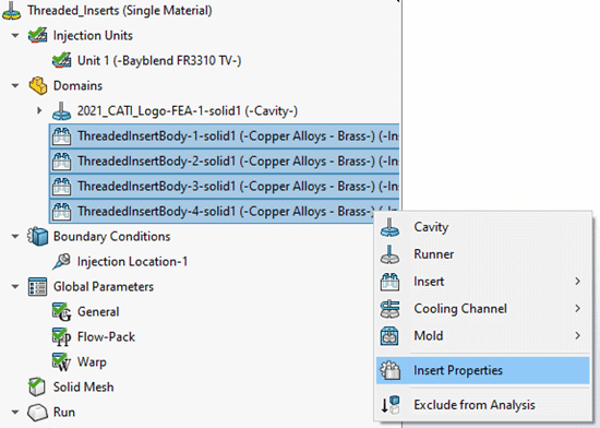
Figure 3.
When creating the mesh for the SOLIDWORKS Plastics study, both the Uniform and the Curvature-based refinement methods will automatically refine the mesh of the insert as well as the cavity around the insert. In Figure 4, the left side shows the refinement at the shell mesh stage while the right side shows section clipping through the insert at the solid mesh creation stage.
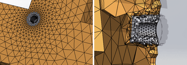
Figure 4.
Analyzing Your Results
After solving the SOLIDWORKS Plastics study with inserts, there are two result quantities that I will focus on – Fill Time and Frozen Area at End of Fill. By reviewing the animation of a Fill Time plot, you can visualize how the insert temperature has a localized effect on the plastic melt front (Figure 5). The molten resin reaches the insert very early in the Fill process, but due to the localized freezing of the resin onto the insert body, the filling near the insert appears to slow down. While this is expected, there are design modifications that can help alleviate this potential molding issue. It is usually recommended to allow for slightly thicker walls around the insert. This allows the resin to flow more freely around the insert while adding more material enabling the plastic to better withstand structural loading conditions. Consult with your injection mold tooling engineers for design guidance!
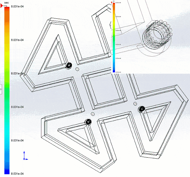
Figure 5.
The second result quantity, Frozen Area at End of Fill, also highlights the temperature differences between the mold cavity and the inserts (Figure 6). The green regions on the plot indicate where the plastic resin has cooled below the glass transition temperature when the injection process has completed. This plot alone does not necessarily indicate a design issue with moldability of the part, but it is something to pay attention to. If too much of the resin freezes near the insert before the end of the injection process, you will end up with a short shot. Again, I recommend consulting with your injection mold tooling engineers to review these results and make educated design changes.
Figure 6.
I hope you have a better understanding of insert molding and how to incorporate inserts into your injection molding analysis. Be sure to reach out to your Computer Aided Technology account manager to begin any discussion on how we can help you with your injection molding analysis needs. Now go make your products better with SOLIDWORKS Simulation!
Bill Reuss
Product Specialist, Simulation
Father, Golf Junkie, Coffee Connoisseur, Computer Nerd
Computer Aided Technology, Inc.