SOLIDWORKS Simulation and Flying – Watch your approach!
Think for a minute, if you will, about what it takes to fly and land an airplane. In this blog, I’ll use the analogy of flying an aircraft to present some fundamental considerations related to performing finite element analysis (FEA) with SOLIDWORKS Simulation, or any FEA tool for that matter! As you will see, these two activities have much in common!
Cessna 152 vs. 340 – Two very different aircraft.
First of all, an important consideration is to know what you are flying and your ability to safely handle its controls. I’m not a licensed pilot, but I took some training in a Cessna 152, and even though it’s been a while, I would probably still be able to fly and land one, albeit with a significant bounce or two! An important realization is that this does not mean that I can fly any airplane! As you can see in the images below, these are two very different aircraft.

The analogy to simulation is to know what package you are running and your ability to use the functionality it offers. What version do you have access to, SOLIDWORKS Simulation Standard, Professional, or Premium? Each level provides additional functionality as shown in the matrix on the CATI Simulation product page. With Simulation Standard I can run linear static and fatigue studies; Simulation Professional and Premium add other study types like thermal, frequency and linear dynamics. In some cases, these advanced studies require a deeper understanding of the engineering principles involved.
Certified instruction is essential.
This brings me to my second point, instruction! Taking lessons from a certified instructor is needed before attempting to fly on your own. Only after the proper level of training can one start to take the controls and safely command the aircraft. In the process, the instructor is there to “take the controls” if you get in a bind. I definitely had to hand over the control a couple of times during my first landing attempts! After passing an FAA sanctioned test, a student becomes certified to fly the aircraft that he/she trained on. This is referred to from the FAA standpoint as “type certification”.
In terms of simulation, do you know what’s involved in correctly setting up the study types at your disposal? Have you taken the training class for the simulation package you are using or reviewed the tutorial exercises? Training from a certified Simulation instructor is available for SOLIDWORKS Simulation. We offer classes that cover all of the packages here at CATI. Also, three levels of Simulation certification are available; Associate, Professional and Expert.
Learn as you go – the real world experience.
One thing I like to emphasize when working with a real design, as opposed to a canned training file, is to learn as you go. Pay particular attention to the important things and how the software handles certain situations. My flying analogy is a situation that developed during one of my lessons. While flying at about 2000 ft. altitude, the door on my side of the airplane suddenly popped open! The instructor and I were both securely buckled in, of course. The instructor immediately seized the opportunity to teach an aerodynamics lesson. He said to me “leave it open and let’s turn the plane using the door.” At his guidance I pushed the door further open, and this “spoiled” the airflow under the wing, causing it to lose some lift. The result was a slow banking turn. It was great to experience firsthand the effect of changing the airflow around the wing. Learn as you go!
To facilitate learning as you go, I recommend starting with a simplified version of the design. You set up a simple analysis on this version and avoid the overhead associated with the complex details. As you figure out things like contact and mesh resolution requirements you add more complexity. In this video, I presented a detailed workflow for setting up an analysis of a boat trailer frame using this technique.
The “Watch Your Approach” analogy.
Finally, let’s consider the phases of the approach and landing process and compare them to steps in the simulation analysis process. The diagram below shows the standard landing pattern for a runway landing. It is the standard method used in aviation to keep all aircraft at a safe distance on the approach to an airport.
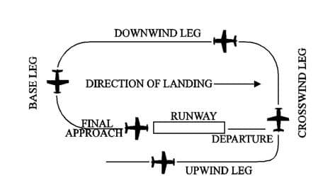
Source: https://www.faa.gov/air_traffic/publications/atpubs/aim_html/chap4_section_3.html
1. Identify the landing point and enter the pattern on the upwind leg – What is the desired end goal of running the analysis?
2. Know the landing pattern at the airfield and start the crosswind leg – What type of study/studies will my end goal require?
3. Get parallel with the runway on the downwind leg – Run a simplified version of the model. We are close to the field but not ready to land.
4. Make a good turn to enter the base leg – How do the results of the simplified model look. Will it require some significant adjustments?
5. Line up the final approach – Running the final version of the model. Have I captured the real world problem accurately?
6. Get centered over the runway, set up a proper flare – Do I have a fully converged solution?
7. Touchdown and final stop at hanger – Publish that report!
We’re safely on the ground and have a quality report to publish, and did not bend any landing gear! Thanks for allowing me to present a few ideas with this flying analogy. I hope that it’s been helpful. Next time you see an airplane flying overhead, think of this analogy and ask yourself “do I use a good approach to my FEA?”
Happy flying!
Kurt Kurtin
Sr. Product Manager, Simulation
Computer Aided Technology