How to Dimension Rolled Sheet Metal Cuts in SOLIDWORKS Drawings
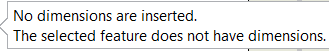
When cuts are made into the flat pattern of a rolled sheet metal cylinder (or semi-cylinder), it is not always easy to extract model dimension data in a SOLIDWORKS drawing. Without proper design intent, detailing the flat pattern positions may not work. It might even require some significant user input for proper documentation. When rolled sheet metal cylinders are not set up correctly, the following error may occur when trying to import dimensions: “No dimensions are inserted. The selected feature does not have dimensions”
Users will then spend more time manually Smart Dimensioning the drawings flat pattern until they get their desired outcome. This is an inefficient use of SOLIDWORKS.
The clever SOLIDWORKS user knows that importing model dimensions in the model is the easiest way of creating saving time on drawings. That’s why Model Items is critical for them to use, rather than using Smart Dimension to manually dimension features on the part. If you’re unfamiliar with Model Items, be sure to check out this helpful blog.
First, I’ll explain how annotations are assigned to views. Then, I’ll share the best practices for making cuts on rolled sheet metal cylinders, and wrap up with how to modify features to support the Model Items command.
How Annotations are Assigned to Views
If you’re an avid SOLIDWORKS user, you may know that annotations are assigned to views based on the planes that the features were created in. If a base-extrude sketch exists on the top plane, the relative sketch dimensions will automatically be assigned to the top plane, too.
Sometimes SOLIDWORKS makes the wrong assignment. In that case, users can re-assign dimensions to other standard views. Under the “Annotations” folder in the FeatureManager Design Tree, one can drag and drop dimensions into the desired view.
We can now modify the sheet metal features to align the standard planes with the flat pattern.
 Standard Process for Making Cuts on Extruded Sheet Metal Cylinders
 Standard Process for Making Cuts on Extruded Sheet Metal Cylinders
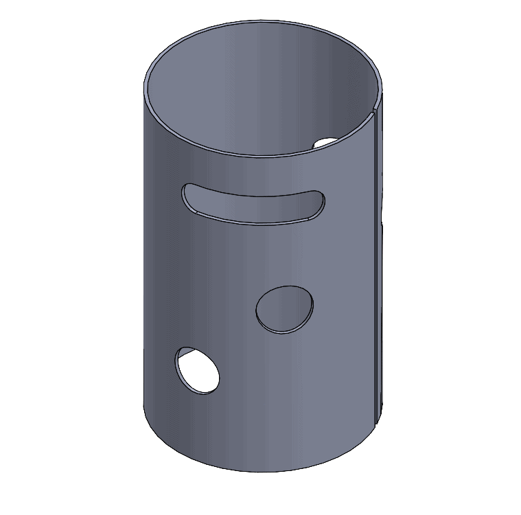
There is a standard process for making cuts as seen in the model depicted here. Some novice users may feel inclined to add these types of cuts after flattening the component using the “Flatten” command. They’ll find out, however, that the cuts cannot be re-folded to get the isometric image they see here. The cuts become suppressed after suppressing the flat pattern.
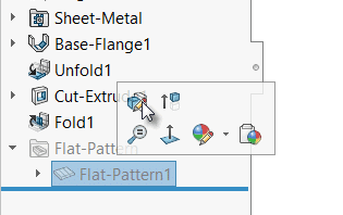
So, what’s the solution? The best practice is to use the “Fold” and “Unfold” commands. By using these commands, we introduce a flat pattern before the Flat-Pattern folder that exists on every Sheet Metal part. This allows us cut geometry and re-roll using “Fold” to get the sheet metal model as pictured.
Let’s see how we can leverage our model data and still be able to use Model Items to avoid the dimensionless feature error we got before.
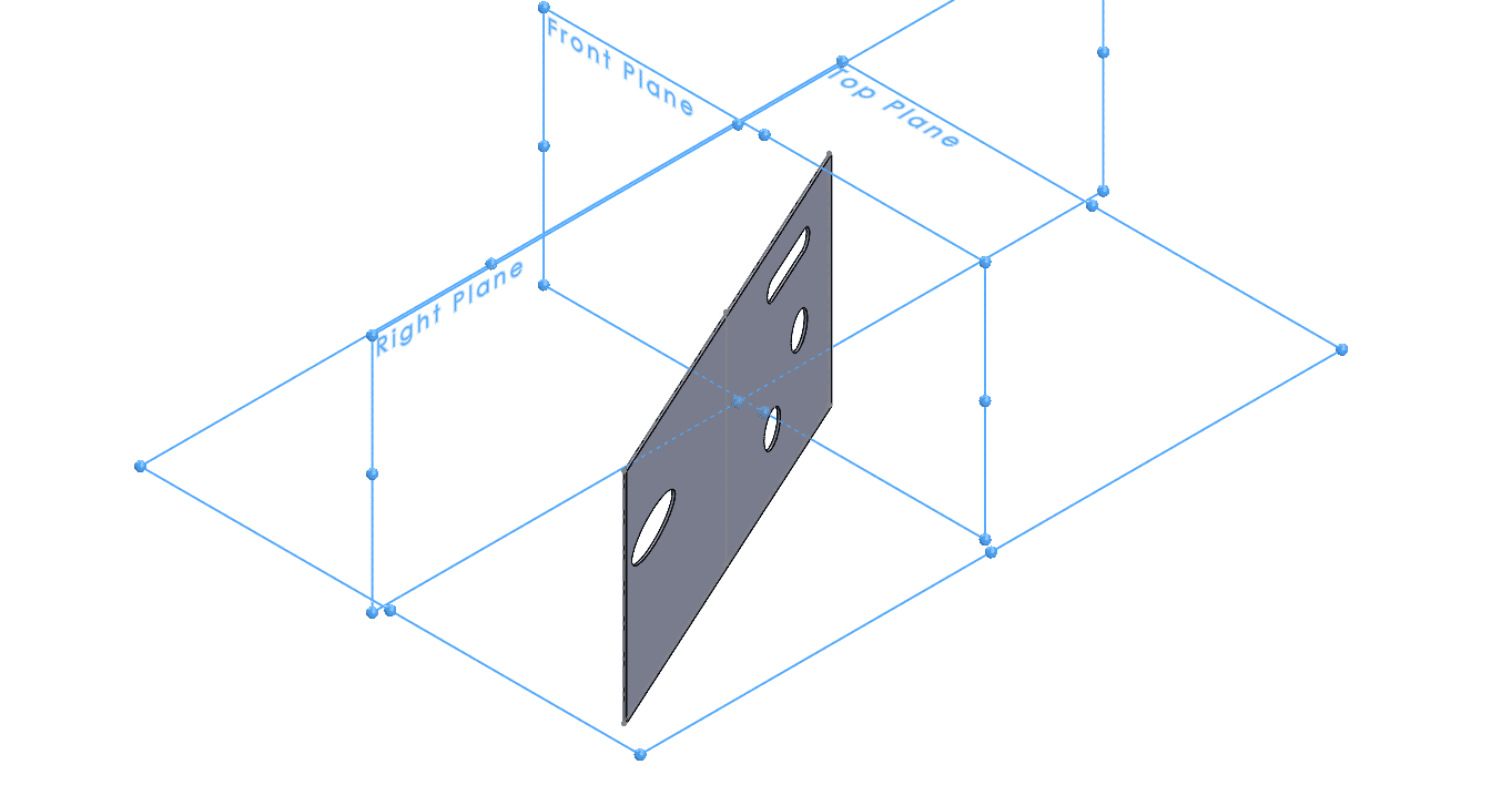
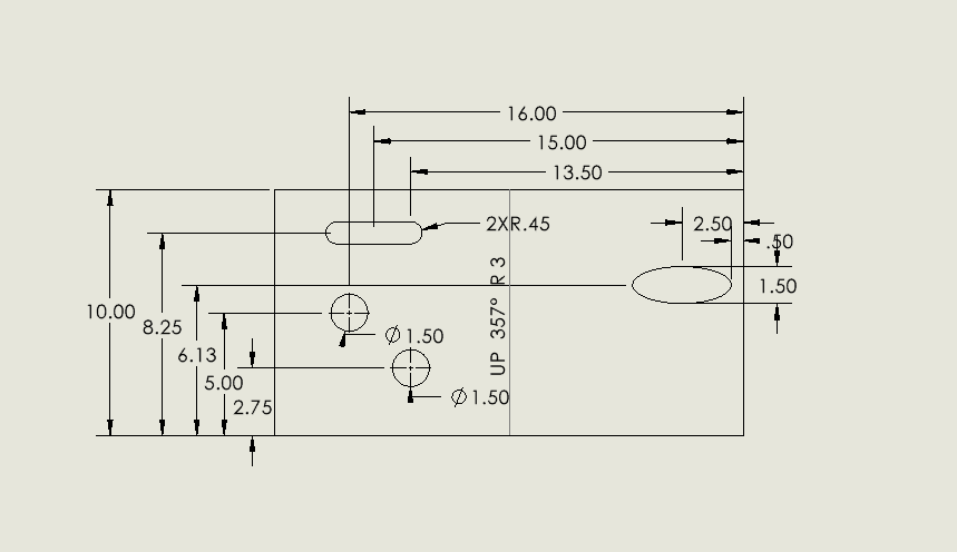
Here are my cut extrusion sketch dimensions that I want to be able to import into my drawing:

Notice how there are no parallel planes when this is in its flattened state.
We get the featureless dimension error because of this conflict. Not to worry, however. We simply just need to re-define the fixed edge this cylinder unfolds on.
Modifying features to Support Model Items
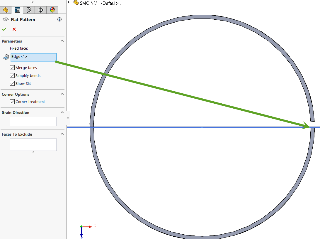
Now that we know how annotations work and know what the issue is, we can address the issue. By editing the Flat-Pattern feature (not folder), we can change the fixed face/edge to an edge that is parallel with a standard plane.
Since no standard planes are parallel with the edge gap, the issue is not with the fixed edge/face, but with the gap altogether. These planes must co-align with the gap.
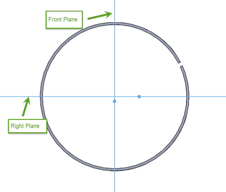
The initial sketch -an open sketch- places the gap randomly. I will align the plane and the gap with a “collinear” relation. This ensures that there will be a plane that is parallel to the face of the gap. This forces the flat pattern onto one of the perpendicular standard planes.
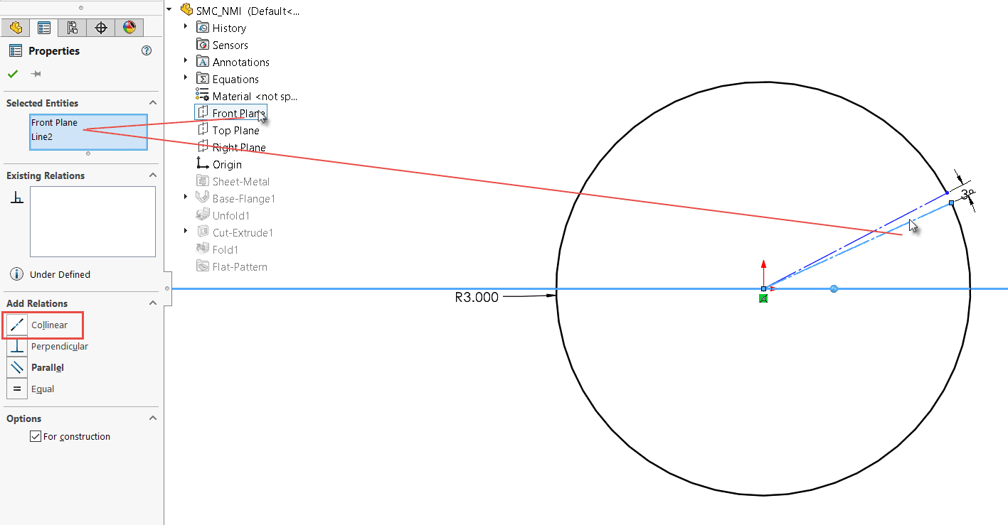 Now, let’s confirm that the Flat-Pattern feature’s edge is aligned with the correct plane. The edge I selected now is parallel with the front plane.
Now I can create a drawing with a flat pattern view. I can now import all my dimensions from the original model feature with Model Items. I can use SOLIDWORKS’ full associativity to drive changes from the drawing back to the model, if necessary. I’ve also saved a significant amount of time by using Model Items instead.
This is an overview on how model dimensions can be imported into rolled cylinder flat patterns. By understanding how annotation views work, users can modify the fixed edges/faces or our sketches and create cut extrusions parallel to standard orthogonal planes for ultimate design efficiency.
I truly hope this has helped you become a more efficient SOLIDWORKS user. If you liked this article, be sure to check out my others here.
Jordan Kleinschmidt, CSWE
Application Engineer
Computer Aided Technology