Requirements on the 3DEXPERIENCE Platform
Quality Design Methodology: Implementing Traceable Requirements to drive a robust and efficient design process.
Quality designs start with requirements. Requirements are the specifications that we design to. Written, verbal or implied, requirements give us the baseline to know when our designs are complete or ready to release/manufacture. Requirements are one of the base pillars of the MBSE (Model Based Systems Engineering) design methodology.
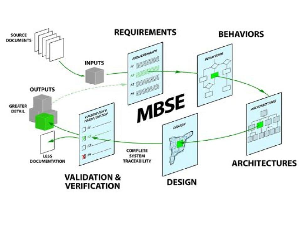
Requirements usually come from 3 sources: Government (or regulatory), Stakeholders and Indirect (“INPUTS” shown above). Regulatory Requirements usually come from sites like the Federal Aviation Agency(FAA) or Department of Transportation(DoT) (For example, DoT requires that all seats in an automobile shall have a seatbelt.). Stakeholder Requirements may come from internal or external end-users of the manufactured item (For example, an airline may have a requirement that the aircraft shall be able to fly 4,000 NM at cruise speed.). Indirect Requirements are derived from other requirements or specifications. (For example, if the 4X4 option is chosen the requirement to have a stronger frame is required and added.).
A Requirement may be “Functional” or “Non-Functional”. Functional Requirements define what a system is to do (For example, “The camera mount shall be able to rotate 360 degrees”.). Non-Functional Requirements define constraints on how the system must do it. (For example, “The aircraft shall cruise at Mach .80 or greater”.).
Non-Functional Requirement categories include: Performance, Environmental, Security, Regulatory (aggregate) and Usability.
Customer design practices rarely include structured and traceable requirements. Dassault Systemes provides a complete design suite on the 3DExperience platform from Requirements through Manufacturing Implementation. This is done using the RFLP data model, CATIA and ENOVIA on the 3DX platform.

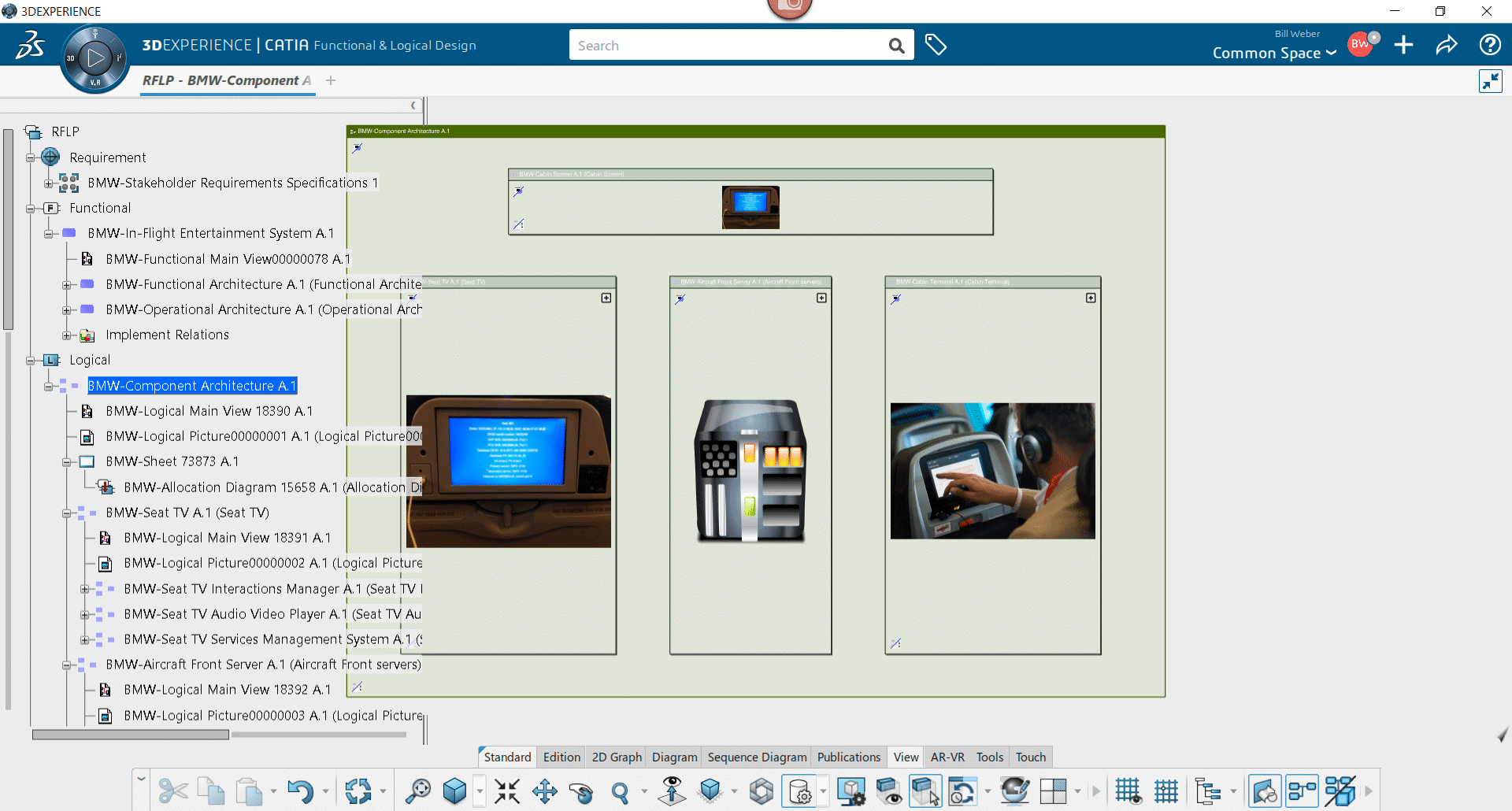
RFLP data model is a DS version of implementing MBSE (Model Based Systems Engineering). R: Requirements, F: Functional, L: Logical, P: Physical Product. This is the future of engineering using 3D models for CAD design, Logical and Functional models to define hardware, functional processes, parameters and formulas within the design and Requirements to make sure the design is meeting stakeholder/needed goals. Currently, RFLP is implemented in CATIA and ENOVIA with certain operations done in each of these applications. (Shown below is the RFLP data model in the “Functional and Logical Design” app in CATIA).
To keep up with industry standards, RFLP is being replaced (deprecated) with more standardized modeling practices. ENOVIA for Requirements, CATIA Magic for Functional and Logical models (based on the SysML modeling language) and CATIA for the 3D designs. This work is ongoing and has a ways to go before it is all deployed and fully integrated on the 3DX platform.
ENOVIA, using TRM and TRA applications will drive Requirement creation and Traceability linking. CATIA Magic will create and control the functional and logical models with formulas, parameters and simulations. CATIA will still be the driving force behind 3D model creation and simulations.
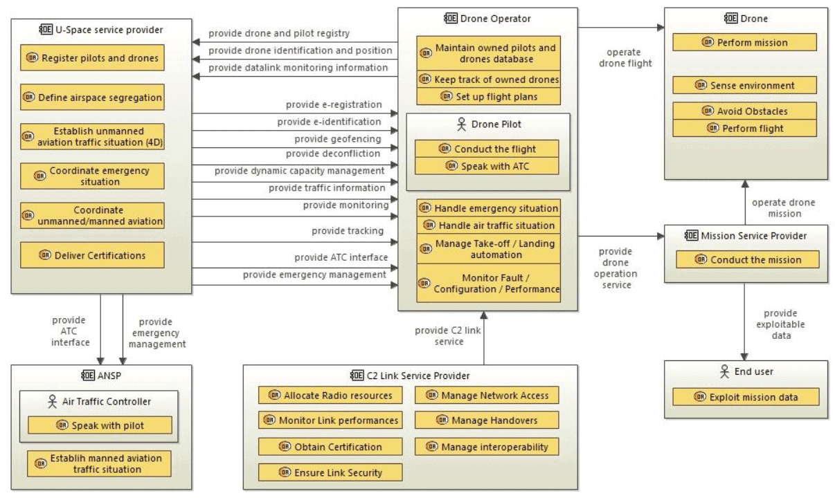
(Shown below is a Drone Operational Model of the Functional Design in CATIA Magic.)
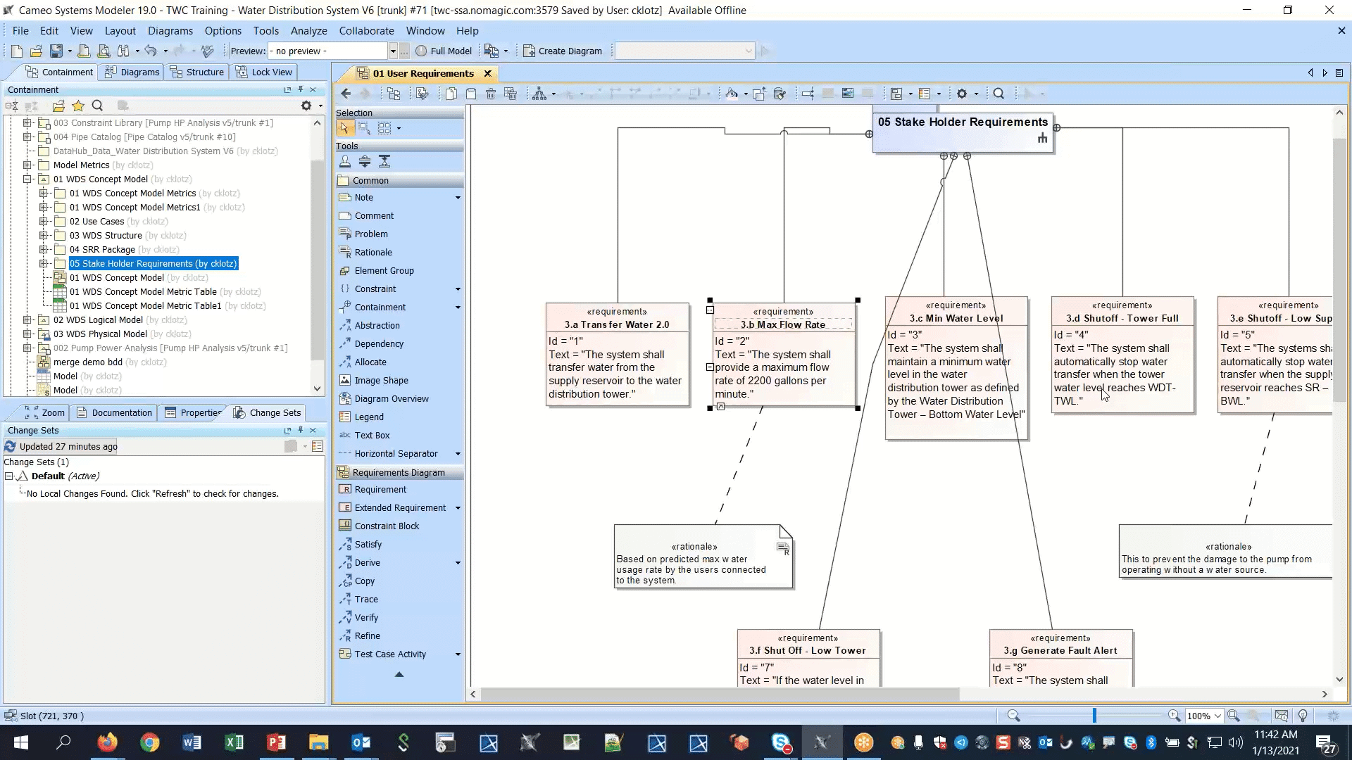
Traceable Requirements Management (TRM) is a way of creating and then being able to loop back from a 3D design or other artifact to determine if all the design criteria has been met and documented. (Shown below are the Requirements for a pumping system in CATIA Magic. Each of these requirements links back (via a separate view) to a sub-system or component that will implement the Requirement, providing Traceability.)
The Traceability app in ENOVIA (TRA) provides the tracing functionalities and graphical views to determine the percentage of Requirements that are linked. You can build a system of Requirements and Specifications that will be a “Scope” that can be traced and linked together.
Systems Traceability will show the user the Requirements that are covered or refined based on a system Scope. Below is shown aircraft avionics specifications (Overview) related to the overall FMS (Flight Management System) and the top-level aircraft systems specification (The aircraft may have 100’s of Specifications). It shows that 100% (green link) of the requirements of the FMS specification are covered by the top-level specification, while 67% (red link) of the Autopilot requirements are covered, 50% (red link) of the Test Cases and Procedures are covered and none (red link with no % on it) of the Auto Throttle Requirements are covered.
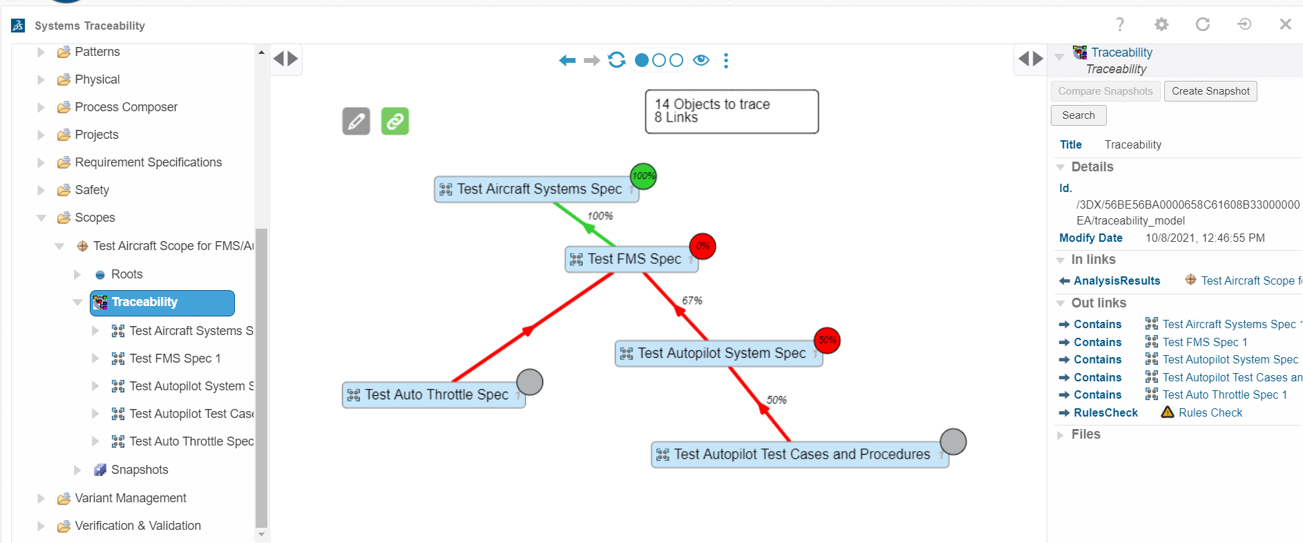
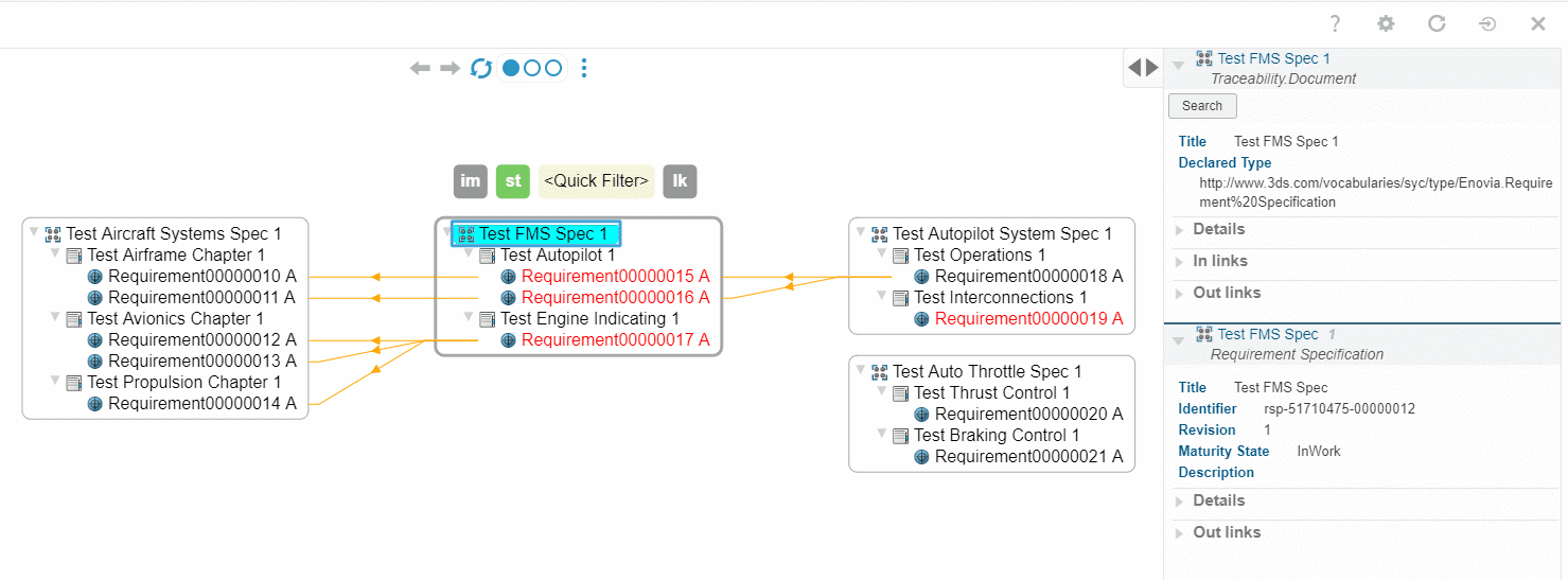
Below we can see the detailed view of the Specifications’ relations. This view shows each of the links between the specifications within scope. In this case, we are focused on the “Test FMS Spec”. Only the direct links are shown in this view. The TRA app will also show which links are “suspect”, giving the user the option to review these links. Links are created as “suspect” by default. The Details Pane on the right side gives the details of the specification of focus. Links can be created here via drag N drop.
Whether using the RFLP data model or using ENOVIA/CATIA Magic/CATIA (for a richer design experience), designing begins with Requirements. Requirements are also the heart of the MBSE design methodology. There must be rules/specifications/parameters for all designs; these come from Requirements, whether the requirement source is Stakeholders, Regulatory or Indirect. Having traceability back to the Requirements is essential. The key to quality designs is good quality, Traceable Requirements.
Bill Weber
PLM Solution Architect
Computer Aided Technology