SOLIDWORKS: Demystifying Mass Moments of Inertia in SOLIDWORKS
What are Mass Moments of Inertia?
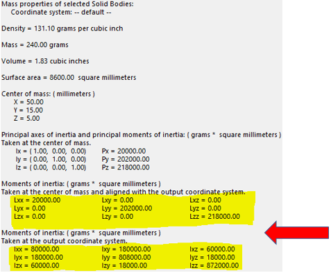
We have all referred to Mass Properties when working with solid models, especially when taking SOLIDWORKS certifications! For the most part, very useful information is available at a glance i.e., Density, Mass, Volume, Surface Area, etc. But how in blazes does someone interpret the rest of the information included in Mass Properties, particularly the numbers at the bottom? What exactly are they telling us?
It all goes back to Moments of Inertia which depend on an object’s mass, shape, and axis of rotation.
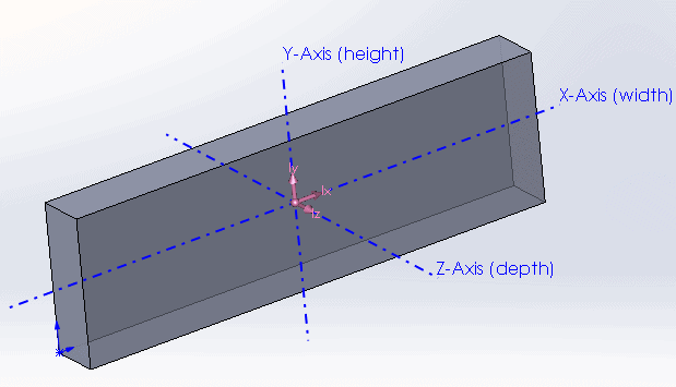
Every object has a Center of Mass that, if suspended in midair from this point, will be perfectly balanced. Taking the following symmetrical object as an example, we can see the principal axes through its center of mass.
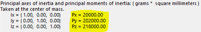
If it is rotated about any one of these axes, we will see Principal Moment of Inertia values which are displayed in units of ML2:
The groups of numbers (3X3 matrices) at the bottom of the Mass Properties window represent Inertia Tensors.
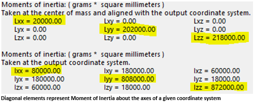
Without getting too technical, the diagonal elements of theses matrices always represent Moments of Inertia about the primary axes of an established coordinate system. Any non-diagonal element represents a Cross-Product Moment of Inertia. Cross-Product MOI is really just an indication of the symmetry of the object. If it is non-zero, then we can expect an off-axis torque or acceleration that will result in a wobble of the object; not a pure rotation. Think of a car wheel being balanced to prevent wobble.
In our example model above, we would expect its cross-product values to be zero for rotation about the COM axes and non-zero about any different axes.
Let’s look at an example of an object that is symmetrical about only one plane (XY):
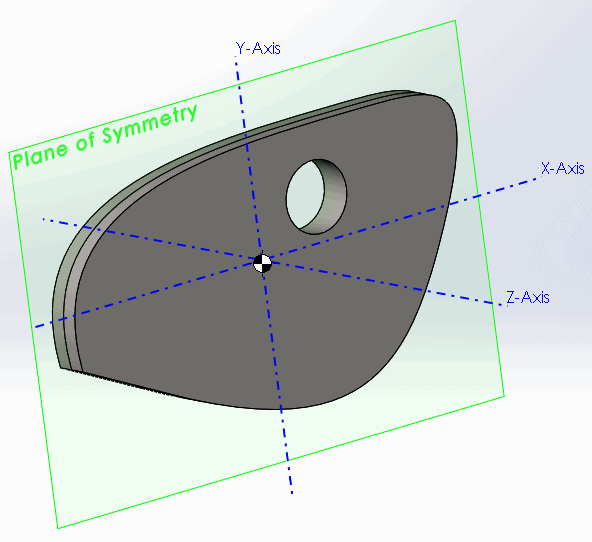
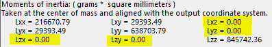
Here we see zero values for all cross-products containing the Z-axis (no wobble in Z-direction). This is because the object’s mass is balanced along this axis in front and back of the plane of symmetry. One way of interpreting the matrix notation is this: If an object is rotating about the X-axis then Lxx is its inertia around the X-axis while simultaneously Lxz is its inertia around the Z-axis.
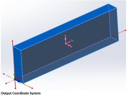
Finally, you’ve probably noticed that Mass Properties also give MOI values about the Output Coordinate System axes. The OCS is the default frame of reference when starting a part, assembly, etc., so its location is dependent on how a model is built. In the following example, the block was created at the default origin extruding forward from the front plane, so its OCS is located at the bottom back-left corner. It’s worth noting that the location of the output coordinate system can easily be changed even after a part is completed, and is done through Reference Geometry (not covered in this article). Therefore, we could technically have it match the COM coordinate system if we wanted.
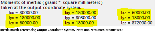
The bottom matrix of numbers in Mass-Properties are calculated referencing the OCS. In this case, it’s easy to envision our example model rotating about these axes and as we would expect, the Moments of Inertia are much larger.
I hope this article cleared up any confusion about the interpretation of Mass Moments of Inertia. And as always, please contact CATI technical support for any questions regarding SOLIDWORKS.
James Carlin
Application Engineer
Computer Aided Technology, Inc.
Interested in Learning More About SOLIDWORKS?
CATI offers a variety of introductory and advanced training courses that are available both in-person and online to fit around your busy schedule. Schedule your training today!
View All SOLIDWORKS Training >>