Forgotten Tools and The Reasons to Use Them: PART 2
Hello again, this week we’ll be looking at design tables, and how we can use them for simple feature suppression. We’ll make variations of a house key to explore how design tables can help us efficiently create configurations of a part.
Every day in manufacturing and design we deal with variation. Multiple formats for multiple applications. Having a way to move back and forth between those designs efficiently saves a lot of time and complication. SolidWorks gives us the ability to create configurations in several different ways. One of the quickest ways to create configurations is by creating a design table.
Design Tables utilize Microsoft Excel to create spreadsheets that house parameters to create a configuration of known part file. Having these parameters in a spreadsheet format allows us two “key” (no pun intended) advantages:
- We get to see all associated parameters at once.
- All associated parameters are displayed in a very organized and familiar format.
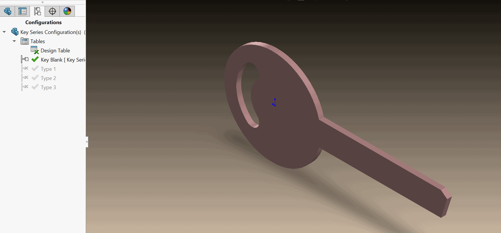
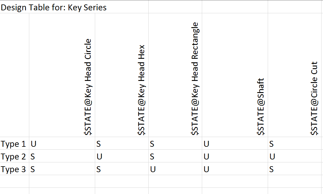
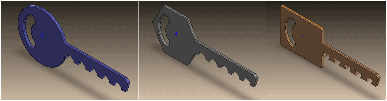
In a Design Table, configurations are listed in rows, while associated parameters are lined up in columns. In this example, we have four total configurations (Including the default Key Blank). Type 1, Type 2, and Type 3 are the other configurations. Each configuration has several features suppressed or un-suppressed to produce the end result.
Let’s look at how this works!
We’ll start with the key blank, which is a pretty simple part to begin with. Just like any other part, this key starts with a sketch to define its profile.
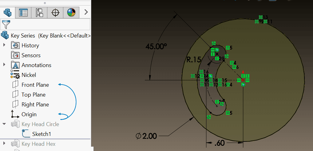
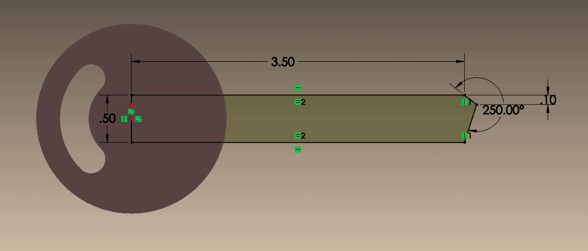
After the sketch for the head of the key, we can create the key shaft. Notice how these two, the key head, and shaft created in two different features. This is important because both features are the variables for our design tables.
Let’s look at our first set of features that make up the key. The key head starts with a circle sketch to create a round key head. This is the default head shape for our blank, but will also be the head shape for one of our configurations. Type 1 should have the following characteristics:
- Round Key Head
- Hexagonal cut shaft teeth
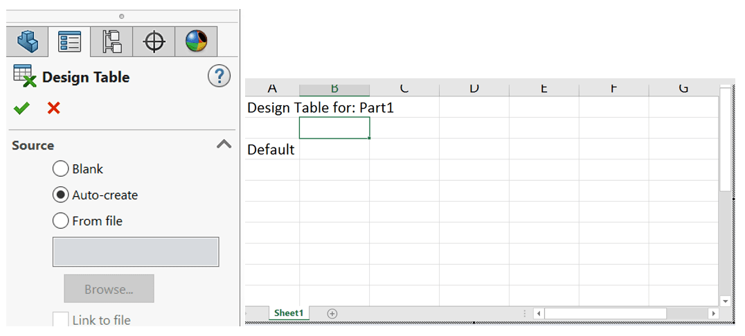
We can see that because of this criterion, we have suppressed those features in the feature tree manager. This can be done via the design table interface. I’ll start my design table by going to the pulldown menus at the top of the screen and clicking on “Insert”, “Tables”, and “Design Table”. This brings me to the property manager for design tables. I’ll go ahead and keep it on the “Auto Create” mode for templates. This will allow me to just move into the standard template for the spreadsheet. I’ll click the green check and SolidWorks will move me into the Excel interface for working with the spreadsheet.
Now I’ll start to label and name my configuration, before adding feature parameters. I’ll enter the name for the first configuration in the cell that says “Default”, and start adding parameters for features by clicking back on the feature manager design tree, and selecting the features that I want to add. In this case, we need the:
- “Key Head Circle”
- “Shaft”
- And “Hex Cut”
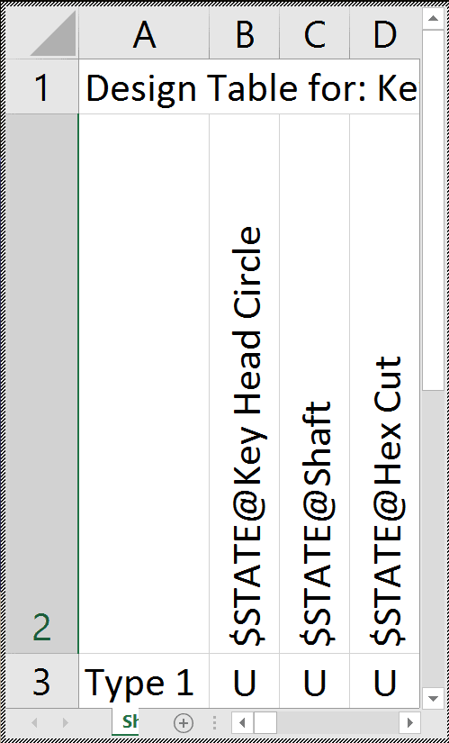
With “Type 1”, we know that we want to show the circular key head, the shaft, and the hexagonal cuts. To reflect this, we’ll mark all the cells under each feature with a “U” for “Unsuppressed”. Now that we have a general format, we can start adding in and marking all the other configurations. With each configuration, a switch logic can be considered. In other words, we’ll switch on (un-suppress) features associated with their configurations, while turning off (suppress) features associated with other configurations. Just for cosmetic reasons, we’ll also add in the fillet features used to smooth key geometry to the columns. Once again, to add a feature to the columns of the design table, we simply need to navigate to the feature in the feature manager design tree, and click on it while in the design table. The end result of the design table should look like this.
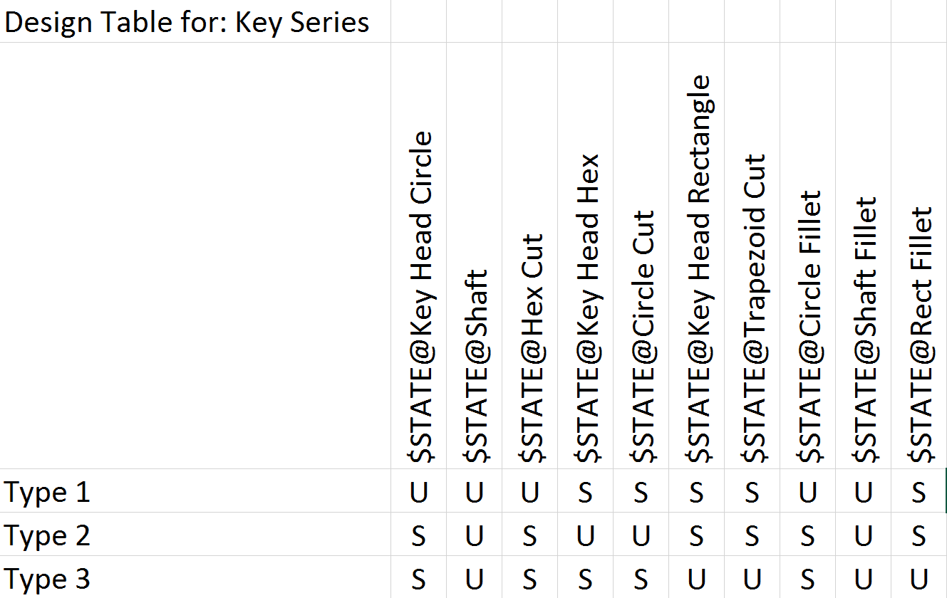
Notice how each configuration has the appropriate feature suppressed or un-suppressed in the individual columns on the spreadsheet. To complete this design table, we’ll click out on the graphics area allowing the design table to close the interface. On closing a dialogue will show confirming the creation of the 3 configurations that just listed. We can confirm the creation of the configurations by clicking on the “Configuration Manager Tab”.
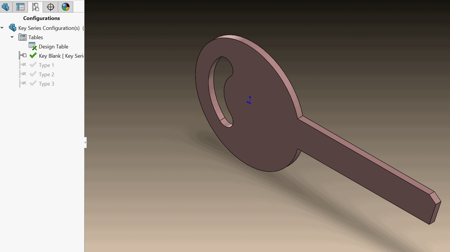
I can confirm these configurations are functional by simply double clicking on each one to update the data set. Using design tables, I’ve created three distinct variations of the same key. I’ve added different display states just for visual reference.
This concludes our discussion on feature suppression with design tables, once again I’m A.S.E. Jay-Shan Jackson with 3DVision Technologies, until next time.