SOLIDWORKS Quick Tip - Odd Angle View Creation
Getting those odd angle views
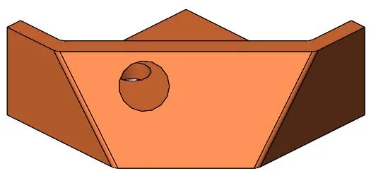
What do you do in SOLIDWORKS when you need to make a drawing of a part with an obscure angled plane? Take this part for an example:
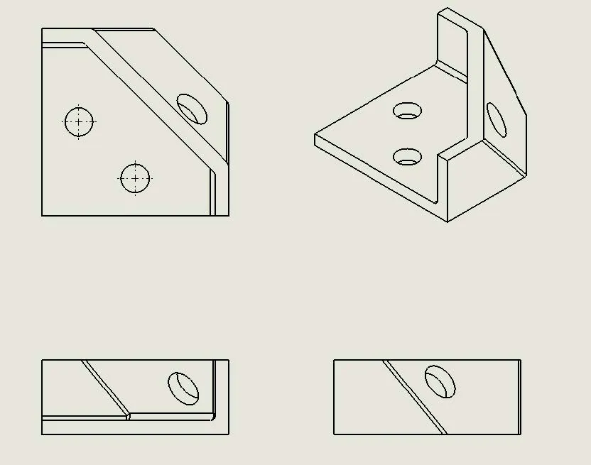
As you can see, the view that is needed for the angled section would be difficult to get to be directly perpendicular to the hole going through it so we could give an accurate dimensional callout. Even a projected view will be difficult using the existing geometry. Luckily, SOLIDWORKS can create this view quite easily. Let’s start with the part file.
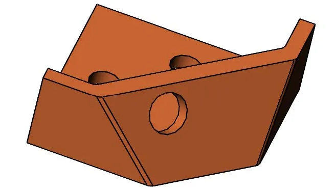
- Open the part file:
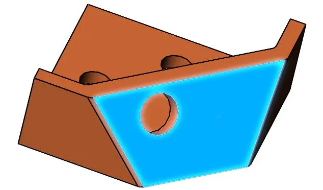
- Select the face that has the hole through it:
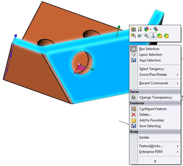
- With the CTRL button held down, select the face that has the edge that I want to be horizontal on my new view. This selection will control the orientation of the view and how it is displayed:
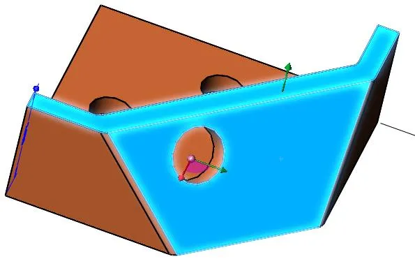
- Once you have both of these planes selected, right mouse click next to the green arrow that is coming out of the plane, and select the Normal to icon:
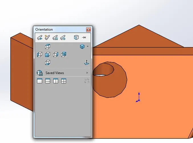
- This rotates the part to look straight on the face with the hole in it, but also rotates it so the second plane we selected gives us the horizontal rotation that we want:
- We can save this view in the model by hitting the space bar to activate the View command:
- With this dialog box active, you can select to save the current view as a saved view for use in your drawing. Select the New View icon:
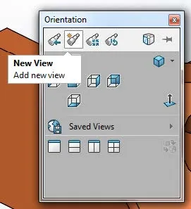
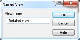
- Name your new view:
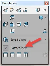
- This now shows up in the Saved Views listing in the dialog box:
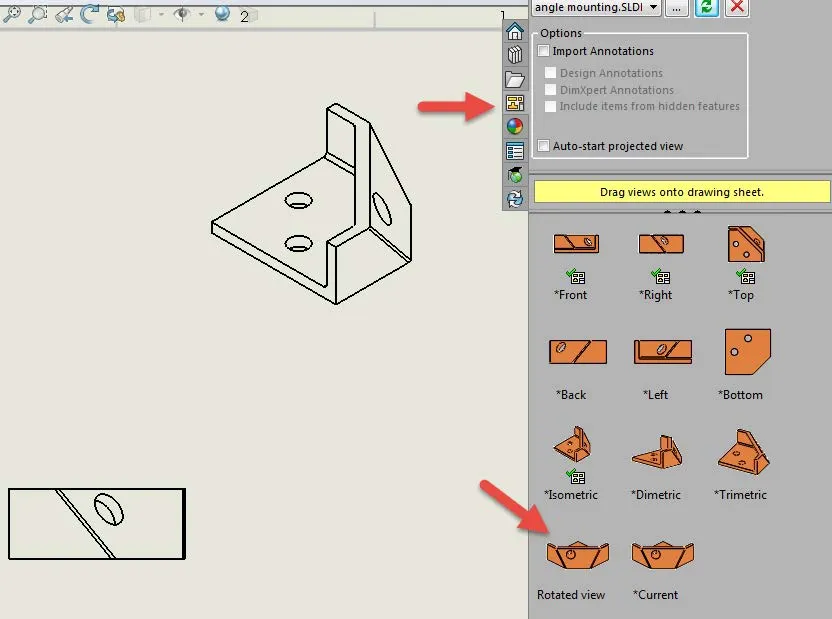
- You can now use this view in your drawing to show accurate dimensions, this view can now be dragged into your drawing and used as any other view.
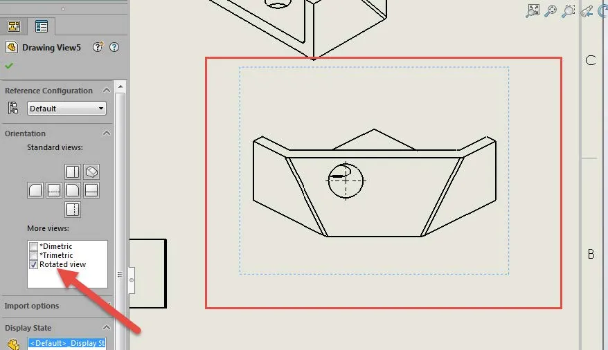
- As you can see from the crosshairs, this view is recognized with accurate diameters that are oriented the way we need to properly detail the features shown.
I hope you found this SOLIDWORKS quick tip helpful. Learn more tips and tricks below.
More SOLIDWORKS tutorials
Inserting Model Dimensions into a SOLIDWORKS Drawing
Scaling a Part in SOLIDWORKS 2 Different Ways
SOLIDWORKS Path Mate Explained
How to Mirror Parts in SOLIDWORKS Two Different Ways
![]()
About GoEngineer
GoEngineer delivers software, technology and expertise that enable companies to unlock design innovation and deliver better products faster. With more than 35 years' experience and tens of thousands of customers in high tech, medical, machine design, energy and other industries, GoEngineer provides best-in-class design solutions from SOLIDWORKS CAD, Stratasys 3D printing, Creaform & Artec 3D scanning, CAMWorks, PLM, and more
Get our wide array of technical resources delivered right to your inbox.
Unsubscribe at any time.