Avoiding Singularities in SOLIDWORKS Simulation
A singularity is a function’s divergence into infinity. Simulation occasionally produces stress (or heat flux) singularities. In this article, we discuss avoiding singularities in SOLIDWORKS Simulation and how and why they occur.
How do they singularities occur?
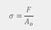
Mathematically, the solver uses matrices to represent the elastic field (displacements of the elements). When a highly localized load is applied, the gradients of the displacement vectors begin to diverge, causing the roots of the matrices to go to infinity. For a simplified explanation, see the stress equation below. Stress goes to infinity due to force applied in a very small area.
Where do singularities occur?
Singularities are usually seen at points, edges, or reentrant corners. Reentrant corners are interior corners, with angles pointing into the part. The high-stress concentrations are usually seen near 90-degree corners, but can potentially occur for any angle less than 180 degrees.
Why don’t singularities occur in real life?
Think of the common case of singularities created on interior corners. In software, that corner is perfectly sharp. In real life, there will always be a slight bend. Also, the part may deform slightly, or “slip”, and allow the faces of the corner to slide against each other. The slight bend and additional friction allow for converging stress.
Tech Tip: "Adjust your legend’s color settings to grey out above the material’s yield point. This prevents singularities from overshadowing other important stress results!"
Is it really a singularity?
The following steps will be used to monitor singularities and determine whether stress results diverge. First, apply sensors in high-stress locations. Secondly, activate the trend tracker to monitor those sensors. Third, use increasingly fine mesh controls in the high-stress regions. As mesh fineness increases in the high-stress fields, the stress sensors will either converge or diverge, viewable in your trend tracker graph.
How to Avoid Singularities
You now understand singularities and have determined you have a singularity in your part. If you choose to ignore your singularity skip to the bottom two bullets in this list. If you want to fix it, you must adjust your part or adjust the settings in your study.
Locate reentrant corners where singularities most commonly occur. Since the force transfer trying to go through that edge is causing the singularity, provide a larger surface area in order to distribute the loads. Fillets or chamfers are commonly used. The pictures below demonstrate this concept.
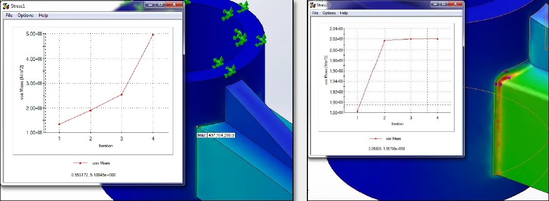
Figure 1. Re-entrant corner vs. fillet
Don’t let the fear of singularities prevent you from defeaturing your models. Remember, sometimes fillets are useful, but they always cause a finer mesh and longer calculation times.
If non-filleted re-entrant corners are unavoidable in your part, design nearby support to prevent crack growth. This support must dissipate the load over a larger surface area before allowing the load to affect the reentrant corner.
- Adjust fixtures
A fixture applied at a point or edge can cause a singularity. To understand why, consider a simple cantilever beam problem. The force being applied on one end of the beam must be counteracted by the fixed end. If the element along the edge of the beam is forced to remain rigid while simultaneously counteracting the force, a singularity is created. In this situation, applying the fixture to the face rather than the edge will prevent divergence.
If fixing the face is not applicable, include the component from the assembly that is creating the fixture. A fraction of the component may also be used as long as it is large enough to allow for complete load transfer. Only replace components with fixtures if the component is much stiffer than the study’s part, or if the fixtures are far removed from important results.
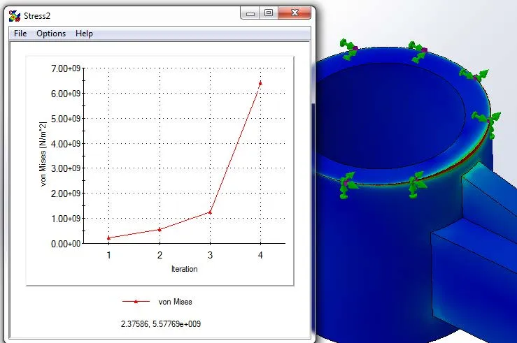
Figure 2. Fixture on edge
Realize that some connectors act as fixtures too. Check if your connector is assuming infinite stiffness by accessing the Solidworks Help menu. If so, adjust your connectors or include the modeled part in the study. The assembly shown below is connected by a tight-fit bolt connector. The tight fit allows the shank to deform, but the nut is still infinitely stiff. The actual bolt needs to be modeled.
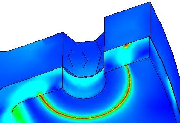
Figure 3. Singularity due to connector
- Adjust loads
Don’t apply force or a heat source at points or small edges. This causes a sharp inflection point in the data input into the deflection equations, which leads to the singularity. If a thin loading area is required, create split lines and apply force to the area between them, as in the picture below. This will allow convergence.
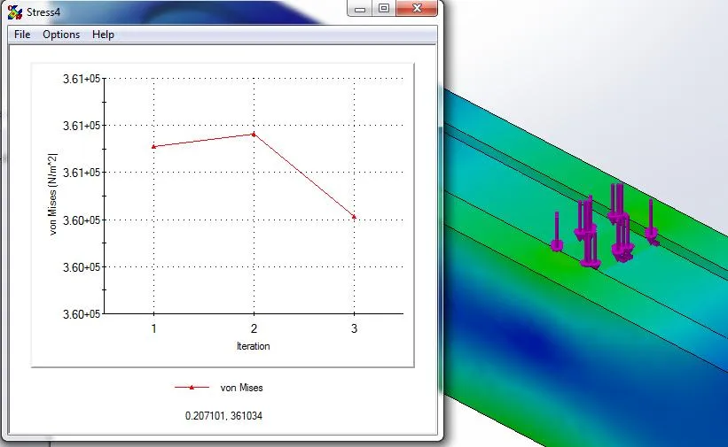
Figure 4. Load on area
- Adjust mesh
Weak singularities may form at the interface of two bonded materials in a thermal study. This is due to the more rigid nature of a bonded element. If necessary, provide a thermal resistance along the interface—this will detract from the implied “perfect” bond.
In nonlinear studies where parts are yielding, a single element’s calculations may collapse if it is too different relative to its neighbors. Fix this by either reducing the aspect ratio in the standard global mesh or applying a mesh control.
- Use Global (slower) accuracy bias in h-adaptive
First, ask yourself, is this singularity ignorable? Usually, the answer is no. However, if you have confirmed that the singularity is solely an idealization error and your part will avoid this high-stress area, or if you are in preliminary design and choose to ignore the singularity, for now, you will want reliable results. More specifically, you will want results that have converged, even if your singularity has not. Using an h-adaptive mesh can give you this confidence.
Apply the “Global (slower) accuracy bias” within the settings of the h-adaptive mesh. While Simulation attempts to converge on strain energy norm, it will overlook singularities created in small areas. If desired, you can create a similar plot to the trend tracker in order to confirm convergence by right-clicking the Results folder and defining an “Adaptive Convergence Graph”.
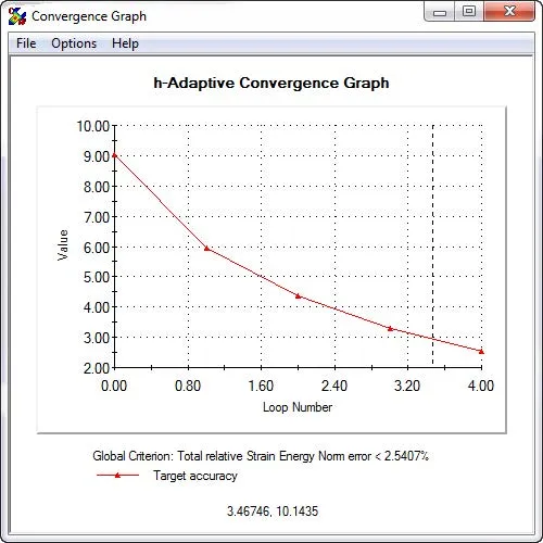
Figure 5. Convergence using h-adaptive mesh
- Set singularity elimination factor < 1.0 in Nonlinear’s advanced settings
Altering the singularity elimination factor should only occur if all other options have been exhausted. Lowering this factor assists in reducing stiffness singularities created from large displacements or high strains. A Nonlinear study is able to recalculate the stiffness matrix of the part at every step, and the singularity elimination factor is applied to these stiffness matrices if stiffness singularities appear.
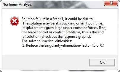
Figure 6. Common nonlinear error
Using this elimination factor usually reduces instability enough for results to be created. You should use this visual feedback to improve your study’s set up so as not to rely on a low elimination factor. Only studies that are highly nonlinear should use a singularity elimination factor for final results. If you are receiving an error, such as the one above, telling you to lower your singularity elimination factor, and your study is not highly nonlinear, then you have an error in your setup. A common reason is a lack of boundary conditions—check your fixtures or your contact sets. A second is incorrectly applying symmetry conditions while the part is under torque.
Summary
Singularities are idealization errors that you can avoid by understanding the assumptions made within the software. First, confirm singularities using a trend tracker graph and increasingly finer mesh. Then adjust your geometry, connections, fixtures, loads, or mesh depending on the location of the singularity. The topics discussed above will help you locate what is causing your singularity and provide a workaround.
Newest SOLIDWORKS Simulation Tutorials
SOLIDWORKS Simulation: No Penetration Contact Set Setup
A Guide for Using Bearing Connectoris in SOLIDWORKS Simulation

About Shivani Patel
Shivani has a background in aerospace engineering, and is the Engineering Manager for southern Texas. She has the Elite certification in SOLIDWORKS and is happy to jump into anything in the SOLIDWORKS licenses. Her main specialty is Simulation - and has spent the past 6 years digging into the Motion Analysis, FEA and CFD programs and supporting many of our oil and gas customers in the south.
Get our wide array of technical resources delivered right to your inbox.
Unsubscribe at any time.