Implementing a Change Form in SOLIDWORKS PDM Professional
An Engineering Change Order (ECO) is one of the standard documents for a change process. Typically, this is a document that tracks changes to any file in the engineering process and transitions between approvers via an email or physical document. SOLIDWORKS PDM Professional is designed to manage engineering documents, so it makes sense that we would use it to manage our Engineering Change Order process.
Let's discuss the implementation steps of a typical change form that will initiate a change to an existing SOLIDWORKS design. Ultimately, we want a separate process/workflow for the change form that also drives files in the existing workflow for our engineering dataset. First, let’s look at what we need to set up when introducing a new file type.
Creating an ECO Process in SOLIDWORKS PDM
In this case, we are creating a new document type called “ECO”. To do this, we will create the following objects in the PDM Administration tool:
- Category for the ECO Document
- Unique Data Card for the specific ECO metadata and variables
- ECO Workflow
To add more control to how we create our new ECO document, the following are optional (yet recommended) steps for the setup:
- ECO Serial Number (control the assignment of a serialized number such as “ECO-1234”)
- ECO template (control the seed file PDM uses, what folder the ECO document is created in, and how PDM names the file)
Today, we will focus on the ECO workflow and how it relates to our design workflow. The following image is our Engineering Data workflow that all our SOLIDWORKS files go through.
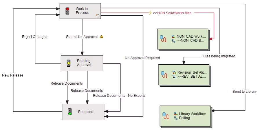
Design Workflow
You can see that a change to a “Released” document is simply a state change from “Released” to “Work in Process” through the transition, “New Release”. Since we want the ECO document to control the change, we can modify our workflow slightly by adding a new “ECO Pending Approval” State.
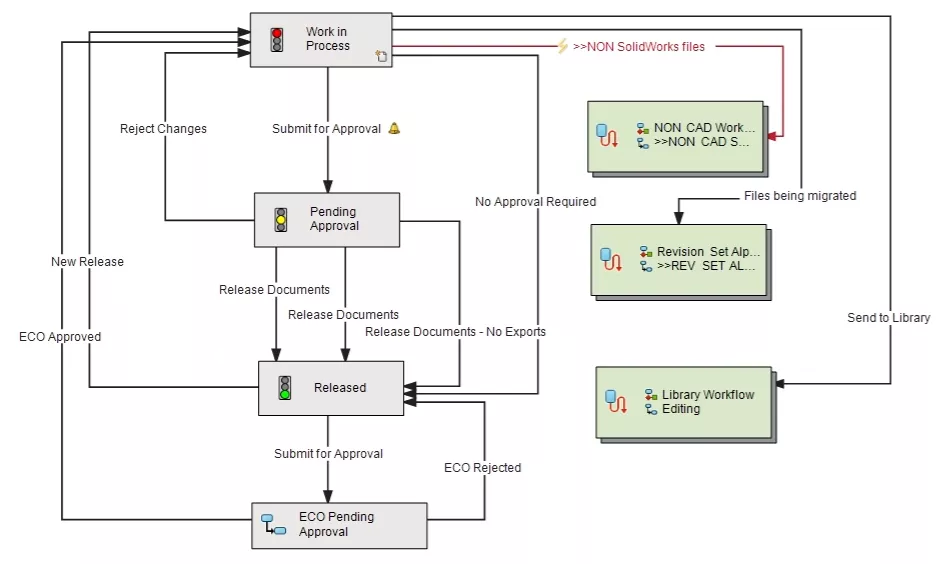
Updated Design Workflow
With the “ECO Pending Approval” state, we now have a way to effectively communicate to others that an ECO is in process and that the design may be changing. Since we want the ECO document itself to go through its own workflow, we need to set that up next. Additionally, we want the approval of the ECO to drive the SOLIDWORKS file to “Work in Process” and, if the ECO is rejected, to return the SOLIDWORKS file to the “Released” state. To do this, we need to simply name the transitions the same so that when we transition the ECO, we can include any affected SOLIDWORKS files in the transition even though they are in a separate workflow.
With all of that in mind, below is our new ECO workflow.
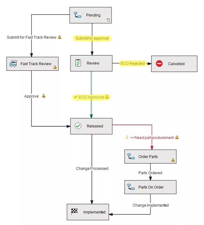
ECO Workflow
You can see that our 3 highlighted transitions in the ECO Workflow are named exactly the same as in our ECO-related transitions in the Design Workflow. Now we have the back-end workflows set up so, the last step is to link the affected SOLIDWORKS files to the ECO before submitting the ECO for approval. To do this, we'll use the Paste as Reference tool.
In my setup, I have an ECO template so that when I create an ECO, it will be named using my serial number generator and placed in the correct ECO folder.
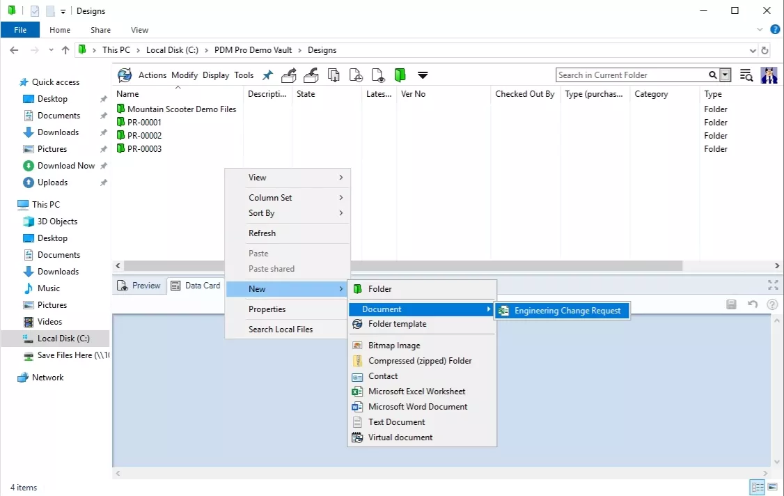
Creating ECO using a PDM Professional Template
Once the ECO is created and checked out , we will select the affected SOLIDWORKS file(s) and use the copy command to then “Paste as reference” to the ECO. This will create a parent/child relationship from the ECO to the affected SOLIDWORKS file(s). Don't forget to check out the ECO before pasting! Otherwise, "Paste as reference" will be grayed out.
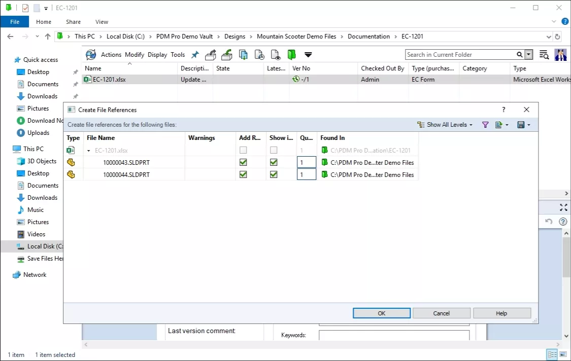
Creating File References
In this example, we have an ECO “ECO-1201” that is linked to two affected SOLIDWORKS part files, “10000043” and “100000044”. With each of our workflows set, once we check in and submit our ECO for approval, the change state dialog will include the SOLIDWORKS part files and allow us to move them to the “ECO Pending Approval” state at the same time.
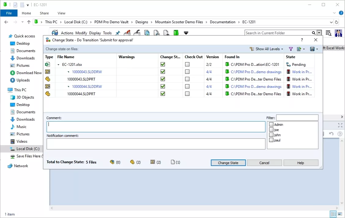
Submitting ECO for Approval
Once the ECO has been reviewed, if it is approved the SOLIDWORKS files will move to the “Work in Process” state or if it is rejected then they will go back to the “Approved” state. So by naming the transitions in two separate workflows the same, any linked documents can be transitioned at the same time as the parent document.
I hope you found this blog explaining implementing a change form in SOLIDWORKS PDM Professional helpful. Check out more tips and tricks listed below. Additionally, join the GoEngineer Community to participate in the conversation, create forum posts, and answer questions from other SOLIDWORKS users.
Learn More About SOLIDWORKS PDM
SOLIDWORKS PDM: Input Formula Aliases
Default Expressions in SOLIDWORKS PDM Data Cards
SOLIDWORKS PDM Network Communication Troubleshooting
How to Check What Version of SQL a SOLIDWORKS PDM Environment is Running
How to Search for Variables That Have Been Left Blank in SOLIDWORKS PDM Data Cards

About Nick Sweeney
Nick Sweeney is a Marketing Specialist with GoEngineer with a focus on software solutions. Nick graduated from The Ohio State University in 2018, completing internships with CATI (now GoEngineer) and DriveWorks Ltd. Before joining the Marketing team, Nick spent 3 years in pre-sales with CATI, giving product demonstrations, leading technical discussions, and creating technical content.
Get our wide array of technical resources delivered right to your inbox.
Unsubscribe at any time.