SOLIDWORKS Lofts FAQ
In this FAQ, we address several questions about SOLIDWORKS lofts.
Question: How are lofts adjusted?
Answer: Sometimes a loft will not generate as desired. There are a few "tips" that can help make a loft the desired shape.
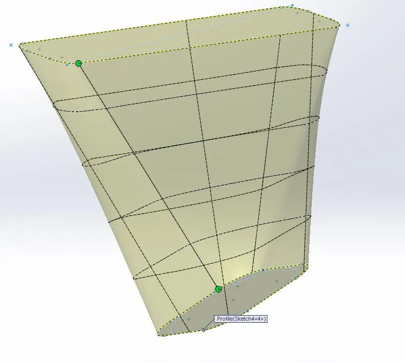
- When selecting the different profiles, be sure to click a place on the profiles edges most adjacent to each other so that you obtain the shortest possible distance for the loft lines, and they do not twist around the section.
- If the loft is still not sufficient, right-click on the mesh, and select "show all connectors." Small points (connectors) appear on the edges of the lofted profiles which can be moved by dragging to the desired location. To add additional connectors right click on the profile edge where a connector is desired and select "Add Connector.”
Question: Are sketches required to create loft features?
Answer: No, sketches can be used as loft profiles however it is also possible to select two surfaces. A loft will be created using the surface edges as the loft profile.
Question: Why are the connectors not shown when editing a loft or sweep with small profile dimensions?
Answer: Connectors are not shown for loft or sweep profiles with very small dimensions (less than 0.1mm).
- You can always create the loft or sweep using profiles with larger dimensions, add and/or move the connectors, and then edit the profiles to decrease the dimension size.
Question: Is it possible to select 3D sketches as a profile for a loft?
Answer: Lofts can use 3D sketch curves to define profiles as well as guide curves. You can even create a Loft from one single 3D sketch containing all of the geometry needed to define profiles and guide curves. But each profile must be made up of geometry that is planar to each other.
- One of the differences between Loft and Boundary is in the way it can work with profiles. The Loft command requires a profile to be a planar sketch or a face. The Boundary allows users to use non-planar curves as section profiles.
Question: When creating a loft or lofted cut with two identical profiles (at different angles), the profile of the resulting geometry is not consistent, why is this?
Answer: A loft feature does not guarantee a uniform cross-section. The only fixed sections are those defined by sketches. The lofted geometry is an interpolation between the sketches, which can be influenced by guide curves and center lines.
- Try using a sweep, with the twist along with the path option.
Question: Why are the loft connectors no longer displayed after changing dimensions?
Answer: Check the sketch used for errors, dangling/irregular sketch relations, or anything that might cause the loft to behave incorrectly.
- The loft connectors will fail to show in the presence of unsolvable conditions when the sketch dimension is modified.
- Once this condition is corrected, the connectors are displayed successfully.
Question: What items are available for Loft within a part?
Answer: The following items can be used for features using the loft command:
- Closed profiles (sketches, curves, or edges) for solid features, open profiles for creating surfaces.
- Faces on solid bodies.
- Surfaces.
Question: Can options in the Loft PropertyManager be permanently set? For example, to always use a face fillet or certain loft tangency conditions.
Answer: Unfortunately, these options cannot be permanently set, even by manual registry edits, as they are hardcoded into the program.
Question: Why does the extended surface, in conjunction with an offset surface generated from a loft surface, produce an edge at the original position?
Answer: If many edges are selected at once, SOLIDWORKS generates a 'split line' at the original edge. A possible workaround is to use the extend command separately.
Expand Your SOLIDWORKS Skillset
SOLIDWORKS FeatureManager: Hidden/Forgotten Commands
![]()
About GoEngineer
GoEngineer delivers software, technology, and expertise that enable companies to unlock design innovation and deliver better products faster. With more than 40 years of experience and tens of thousands of customers in high tech, medical, machine design, energy and other industries, GoEngineer provides best-in-class design solutions from SOLIDWORKS CAD, Stratasys 3D printing, Creaform & Artec 3D scanning, CAMWorks, PLM, and more
Get our wide array of technical resources delivered right to your inbox.
Unsubscribe at any time.