Dimension Precision Settings: Leading and Trailing Zeroes
SOLIDWORKS Leading and Trailing zeroes options are located in your Document Properties. Under Zeroes in Document Properties > Drafting Standard > Dimensions, there is a set of four dropdown menus - one controls the display of Leading zeroes while the other three control Trailing zeroes.
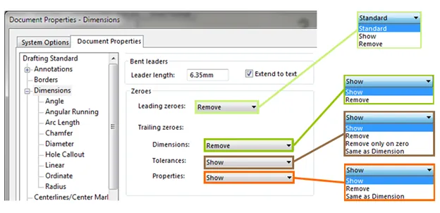
There are three options for how Leading zeroes will be displayed: Standard, Show, and Remove. As you might guess, Show will set Leading zeroes to show, and Remove will hide them. If you pick Standard, whether or not Leading zeroes will show is determined by the overall drafting standard - ANSI, ISO, etc. This is set in Document Properties > Drafting Standard.
With the three Trailing zeroes dropdown menus, you can independently control the display of Trailing zeroes for Dimensions, Tolerances, and Properties. You can hide or show Trailing zeroes for Dimensions. Tolerances can also be set to Same as Dimension, in which case it will follow the setting for Dimension, or Remove only on zero. This shows Trailing zeroes unless the value is zero. Properties can be set to Show or Remove Trailing zeroes or, like Tolerances, to Same as Dimension.
We cover these settings in this SOLIDWORKS quick tip: Trailing Zeroes for Dimensions, Tolerances, and Properties.
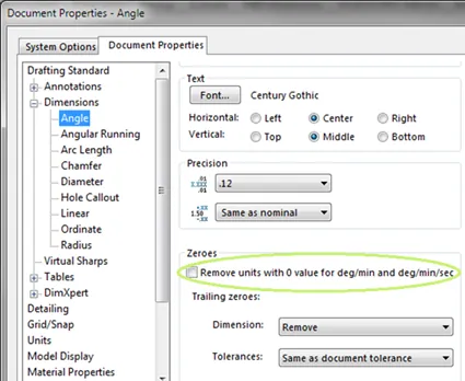
The settings for Leading and Trailing zeroes set in Document Properties > Drafting Standard > Dimensions apply to all dimension types except Angle and Angular Running dimensions. This is intended behavior. Both of these kinds of dimensions have their own Zeroes section. In it, you can set Dimension and Tolerance Trailing zeroes to Show, Remove, or follow the settings in Document Properties > Drafting Standard > Dimensions settings with the "Same as document tolerance" option.
Additionally, there is a checkbox for "Remove units with 0 value for deg/min and deg/min/sec". To take an example from a SOLIDWORKS Help article, checking this box would make 73º0'37" display as 73º37".
Pre-2018 Leading and Trailing Zeroes Options
In SOLIDWORKS 2017 and earlier releases, "Smart" is an option for Trailing zeroes.
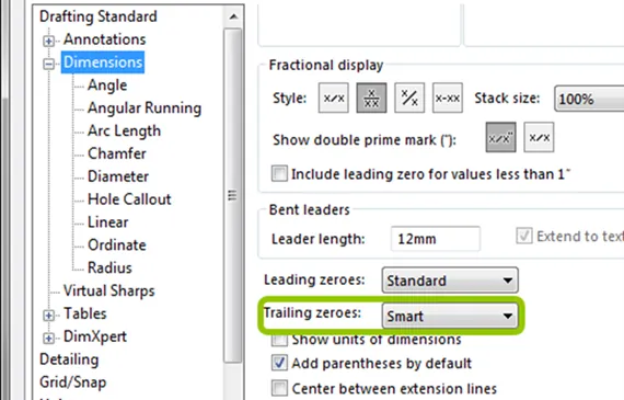
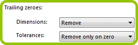
This removed zeroes only for whole metric values. The equivalent in SOLIDWORKS 2018 and on would be to set Dimensions under Trailing zeroes to "Remove" and Tolerance to "Remove only on zero".
Precision and Trailing Zeroes
When Trailing zeroes are set to show, zeroes are added up to the number of decimal places specified in the Primary precision section of that kind of dimension's page. For example, a linear dimension with a value of half an inch will display as 0.50 if both Leading and Trailing zeroes are set to show and, on Document Properties > Drafting Standard > Dimensions > Linear, the Primary Precision for Unit Precision is .12.
Because Trailing zeroes are so closely linked to precision, communicating information about precision is the primary reason to display Trailing zeroes. Let's take a step back and discuss how and where your Precision is set in your Document Properties.
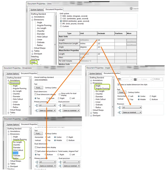
There are three places where you will see options for Precision in your Document Properties: in Document Properties > Drafting Standard > Dimensions, in the subpages under Dimensions for specific kinds of dimensions (e.g., Document Properties > Drafting Standard > Dimensions > Linear), and in Document Properties > Units. As described above, when you create a dimension, SOLIDWORKS will display it using the precision specified on that kind of dimension's subpage. This value can be set to be different than what's on Document Properties > Drafting Standard > Dimensions. However, the precision on specific dimensions’ pages is dependent on the precision listed on the Dimensions page; if the Dimensions page changes, that change will propagate to the individual dimensions’ precision values.
There is a top-down override hierarchy to SOLIDWORKS’ dimensions precision settings.
For example, if my Linear unit precision is set to .12 and I then go to Document Properties > Drafting Standard > Dimensions and set the Unit Precision there to .123, that change will propagate to Document Properties > Drafting Standard > Dimensions > Linear and all other subpages except the ones for Angle and Angular Running.
Document Properties > Drafting Standard > Dimensions has a similar relationship with Document Properties > Units. On the Units page, if a change is made to the Decimals column for Length (the one under Basic Units), that change with propagating to Document Properties > Drafting Standard > Dimensions. This change to Unit Precision on Document Properties > Drafting Standard > Dimensions propagates down to the dimension type subpages. Changes to the Decimals column for Angle on the Units page affect Document Properties > Drafting Standard > Dimensions > Angle.
Related Articles
Trailing Zeroes for Dimensions, Tolerances, and Properties: SOLIDWORKS Tips and Tricks

About Lauren McGarry
Lauren McGarry is a Certified SOLIDWORKS Expert based out of San Diego, California. She earned her Bachelor of Science degree from Case Western Reserve University and has been with GoEngineer as a Technical Support Engineer since 2016.
Get our wide array of technical resources delivered right to your inbox.
Unsubscribe at any time.