How to Scale a Part in SOLIDWORKS
From time to time, SOLIDWORKS users may need to apply a scale to a part. Scaling can be done at any point in the tree but may negatively affect downstream features and sketches and doesn’t change the upstream features and sketches, so the sooner the better. A Design Table can also be used to keep it all parametric and may be a better option. In this guide, we cover both methods of scaling a part in SOLIDWORKS and visualize the differences.
Two ways to scale a part in SOLIDWORKS:
- Scale Tool (Insert > Molds > Scale)
- Via a Design Table (Insert > Tables > Design Table)
Scale Tool
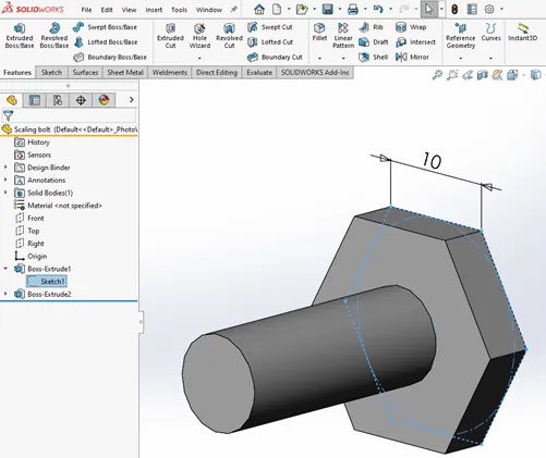
First, a look at the part with no scaling:
Use the Scale Tool from the mold tools tab (or Insert > Molds > Scale). In this example, I have chosen to scale about the centroid, uniformly by two (double), notice the unchanged dimension (10).
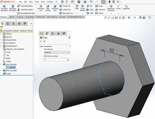
The scale feature takes an existing body and scales it up or down as required.
While this may be acceptable in some circumstances, it’s not parametric and does not update dimensions within the previous features.
Design Table
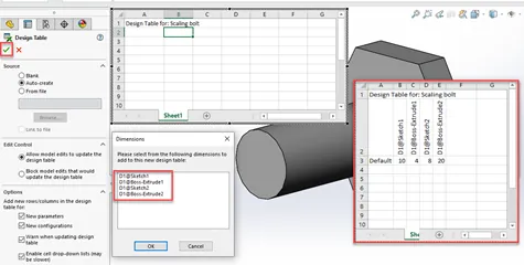
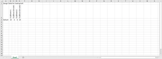
Now, I will take advantage of the Auto Design Table functionality within SOLIDWORKS from the dropdown selection above (Insert > Tables > Design Table). I’ll leave all the default settings and Auto-create; there will be a popup to select what dimensions I’d like to include in the design table. I’ll select them all. SOLIDWORKS will generate the table.
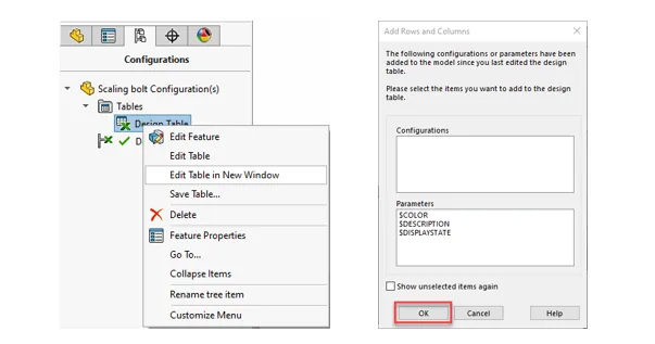
I’ll edit the Design Table using Excel outside the user interface by selecting the Configuration Tab, expanding Tables, and right-clicking on the Design Table. Select Edit Table in New Window. As the Excel window opens, I’m prompted to select items since the last edit, select OK, and the table is in full view inside Excel.
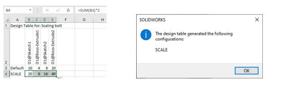
Now, I’ll add a new configuration by typing in a new configuration name and adding a scale equation (= dim * 2), doubling the overall size in the new configuration with it propagated to all dims in the model. Save and exit the Excel spreadsheet. A message appears for the new configuration. Hit OK.
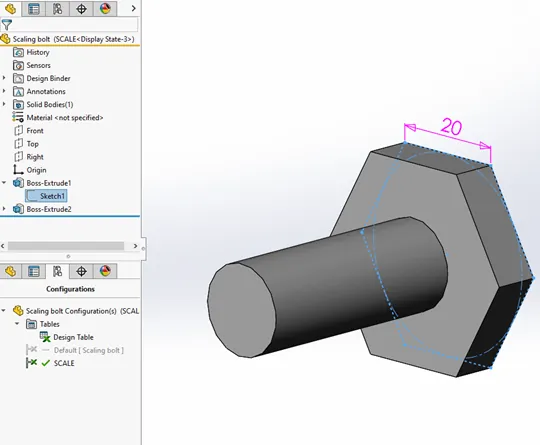
Now, if I change the part configuration to the new SCALE configuration and select the sketch that initially showed as a “10” dim, it will show as 20.
Overall, the Design Table offers more specific control over what is scaled and by how much. The Scale feature quickly applies a uniform scale to fully developed solid bodies regardless of how they were constructed.
More SOLIDWORKS Tutorials
Easily Save SOLIDWORKS Configurations as Separate Parts
SOLIDWORKS Path Mate Explained
How to Mirror Parts in SOLIDWORKS Two Different Ways
Using Cosmetic Threads: SOLIDWORKS Best Practices

About Randle Wood
Randle is a Technical Support & New Products Specialist and has been with GoEngineer since 2009. He has a Bachelors of Science in Industrial Design and has been a SOLIDWORKS user since before the turn of the century.
Get our wide array of technical resources delivered right to your inbox.
Unsubscribe at any time.