SOLIDWORKS Mold Tools: Split Line & Parting Line Explained
If there’s a need to extrapolate information about creating a mold, SOLIDWORKS comes bundled with a set of Mold Tools that’ll make it simpler to analyze any mold design. In this blog, we’ll be discussing how to use the split line and parting line commands to help set up a model for an eventual tooling split.
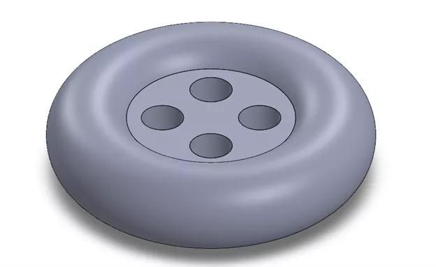
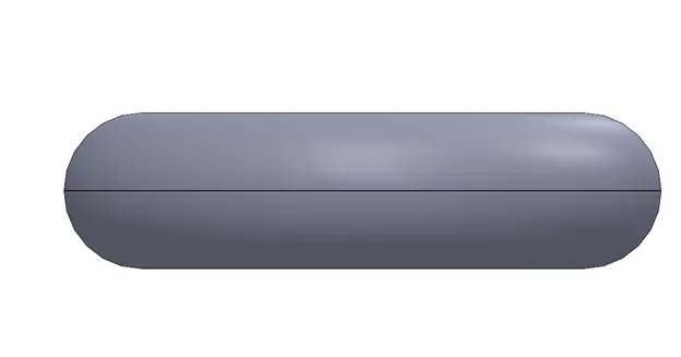
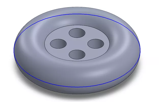
The following example uses a shirt button design, where the outer surface will act as the face for where this feature is added. When designing a mold, an edge is visible to indicate where this split happens, and luckily, we have two sets of tools that can generate this for us.
Related Article >> SOLIDWORKS Mold Tools - Draft Analysis and Scale
SOLIDWORKS Split Line
First up is the Split Line command. This command is generally useful when we need to create additional faces on a model without altering the geometry.
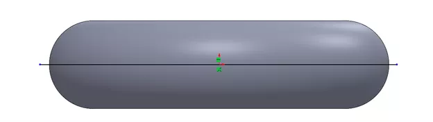
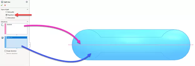
To create a split line, we can either use a sketch, plane, or another solid body in the vicinity. As shown, a sketch line can be drawn that stretches all the way across the space, which is then acting as the projection of the edge.
In the split line PropertyManager, the projection type will then be used by selecting the sketch line.
When completed, this edge marks the location of the split, and we can then go ahead and generate a parting line afterward.
Related Article >> SOLIDWORKS Mold Tools - Shut Off Surfaces, Parting Surfaces, and Tooling Split
SOLIDWORKS Parting Line
Another option is to use use the Parting Line command, which includes an option for splitting the face. From a previous feature called Draft Analysis, SOLIDWORKS references the areas where the positive and negative areas touch.
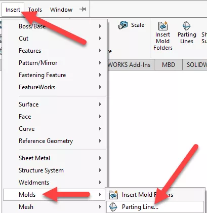
In the Parting Line tool, we’ll designate our neutral plane and draft angle and, upon closer inspection, the Split Faces option can be checked, which creates the split line. Once done, we can head over to the parting line window and select the new visible edge.
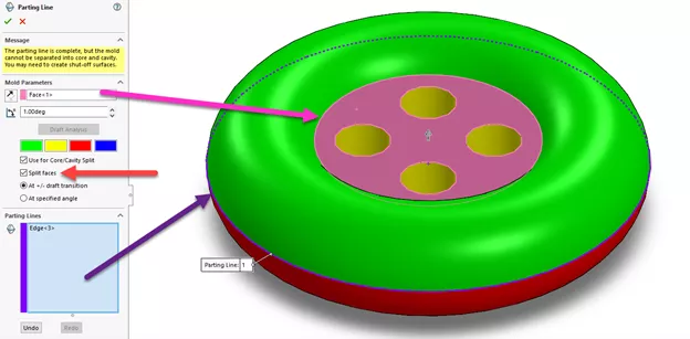
The Parting Line feature encompasses a bluish entity for ease of visibility on where the split is. The next steps will be to continue with the additional Mold Tool features, such as the tooling split.
Whether the split line is added before or during the creation of the Parting Line feature, the tools available inside SOLIDWORKS ensure every model can depict the necessary geometry for analyzing and creating molds.
See a live demonstration using Split Line and Parting Line in the SOLIDWORKS video below.
More SOLIDWORKS Tutorials
How to Use Layers in SOLIDWORKS Drawings
SOLIDWORKS Display Scaling Solutions
Inserting Logos Into SOLIDWORKS Parts and Drawings
SOLIDWORKS Copy and Paste Features: Same or Different Parts

About Jackie Yip
Jackie Yip is a Technical Support Engineer at GoEngineer. When Jackie isn’t assisting customers or teaching a SOLIDWORKS Essentials class, he enjoys road biking and keeping up on the latest tech trends.
Get our wide array of technical resources delivered right to your inbox.
Unsubscribe at any time.