Using the Curve Through XYZ Points Tool in SOLIDWORKS
In one of my recent SOLIDWORKS training classes, a student asked, “Can I use an Excel file to create a 3D sketch that can be then swept?” The answer is yes, and I decided to show him and the entire class the cool feature in SOLIDWORKS called Curve Through XYZ Points. The feature allows you to make some amazing parts that might otherwise cost you many hours of consternation.
Getting data points into Excel
I started by opening Microsoft Excel and created a new file using the blank worksheet template. Once opened, I created a table that had data columns X, Y, and Z. Then I filled in my Excel data columns with several rows of numbers.
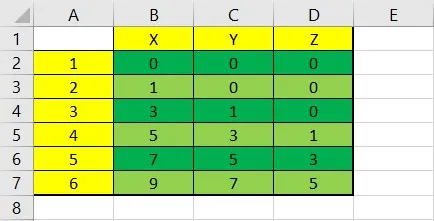
As you can tell by the image to the right, I kept it pretty simple. I saved the file and it was ready for the next step.
Get a text file in Notepad
There are several ways to get data from Excel to Notepad. I am old school so I opened Notepad and started a new file. I then went back to my Excel file, used a bounding box to capture all my coordinates, and copy the data using CTRL-C. Then I switched back to Notepad and pasted the data using CTRL-V.
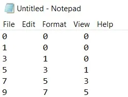
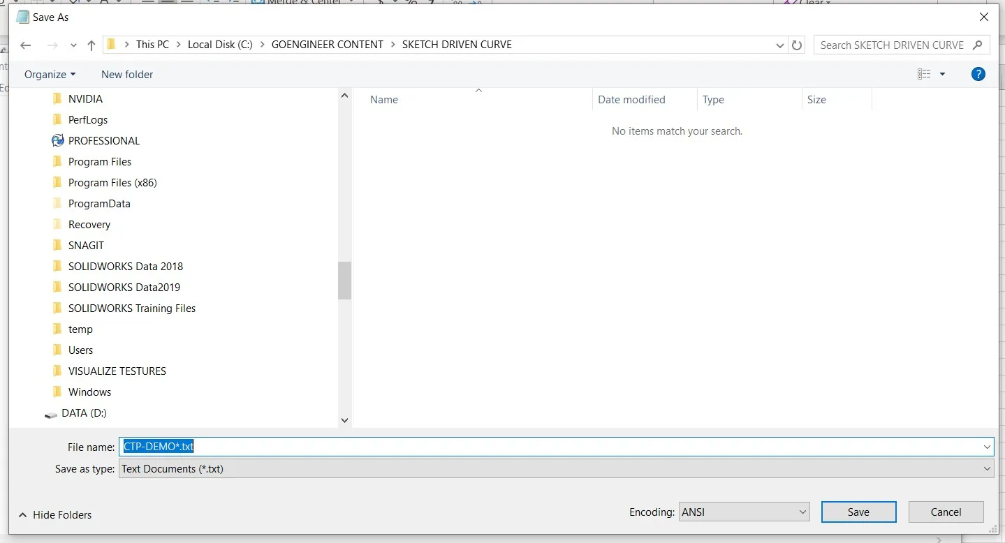
I then saved the file for this example; I named the file CTP-DEMO.TXT (see image below).
Get the data into SOLIDWORKS
With SOLIDWORKS open I started a New Part File with the units set to inches.
The command Curve Through Points XYZ can be found here:
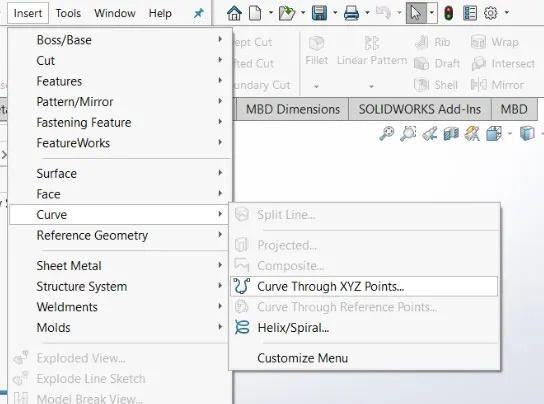
INSERT > Curve > Curve Through Points…
(Note: I am not in sketch mode nor did I activate a plane to start a sketch. The coordinates that are entered into the text file will be automatically added, starting on the front plane. Think 3D sketching.)
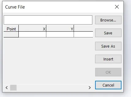
A Curve File pop-up window will open and ask you for the location of the file.
Click on Browse and go find the file with your coordinate data. In my case, we called it CTP-DEMO.txt.
When you find your file and add it to the Curve File pop-up window, you should notice a yellow sketch on your SOLIDWORKS screen.
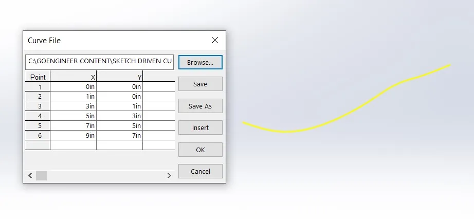
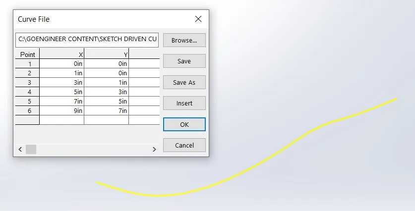
Click OK.
Your pop-up window will automatically close and your sketch is now blue. In the feature tree, you will see a feature that was added called Curve 1.
(Note: I am in ISO view in the image below.)
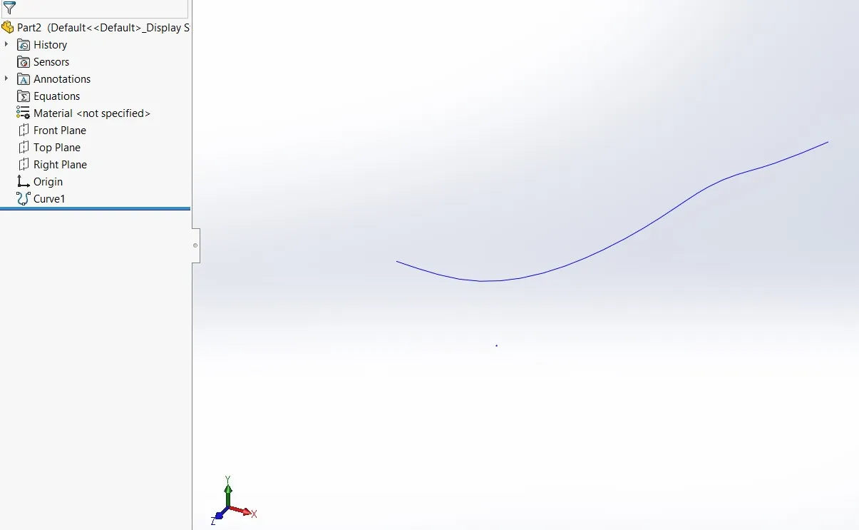
The blue line is a curve that was created using the coordinates from the Excel file that we imported into Notepad and then into SOLIDWORKS.
To edit Curve1, right-click on it and click Edit Feature, and it will take you back to the Curve Line pop up window so you can edit the data.
Sweep the Leg
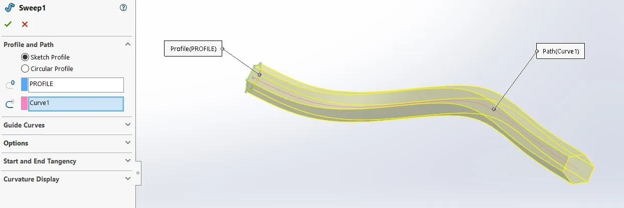
In our example, we started with an initial coordinate of 0,0,0; this allows me to start a sketch of a profile on the right plane. Once fully defined, I exited the sketch and renamed the sketch as PROFILE.
I then used a Swept Boss/Base using the sketch PROFILE for the Sweep Profile and the sketch Curve1 as the Path. Hit the green check and you have a swept part along a path using the coordinate system.
Support
If you get stuck, GoEngineer support is ready to assist you so call us at 1-888-559-6167. Now “GoEngineer” something amazing!
More SOLIDWORKS Tips and Tricks
Dimension Precision Settings: Leading and Trailing Zeroes

About David Cersley
David has been using SOLIDWORKS since 2005 across multiple industries most notably Golf Club Design. He owned and operated a successful design and consulting company that used SOLIDWORKS to bring napkin sketches to production. The industries he's been a part of range from Medical, Aquaponics, Forging, CNC Shops, Roto-Molding factories. He is a proud father to daughter Emmaline (8) and is a husband of 19 years. He is a two-time Ironman finisher and recently qualified for the Boston Marathon.
Get our wide array of technical resources delivered right to your inbox.
Unsubscribe at any time.