Creating Custom Sheet Metal Forming Tools in SOLIDWORKS
Forming tools are a great way to add specific geometry to a sheet metal design. This can range from louvers to lances, to dimples, but forming tools can also help add text or logos to a sheet metal design. This article will help you create custom forming tools in SOLIDWORKS and apply them to a sheet metal model.
Geometry Creation
The first step is to create a part that represents the shape of the form you wish to make. In this case, I have chosen the GoEngineer logo.
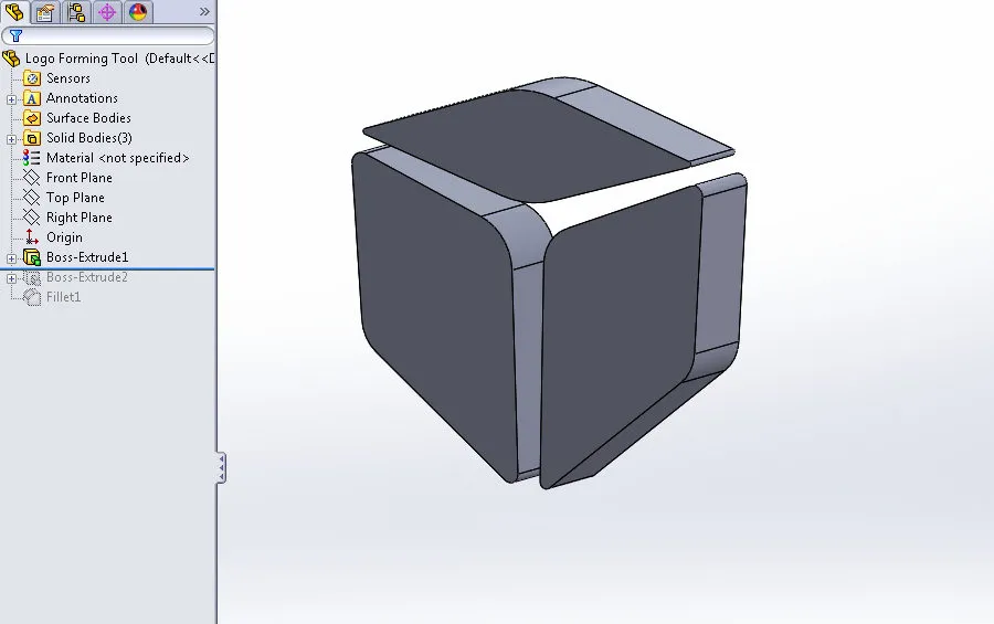
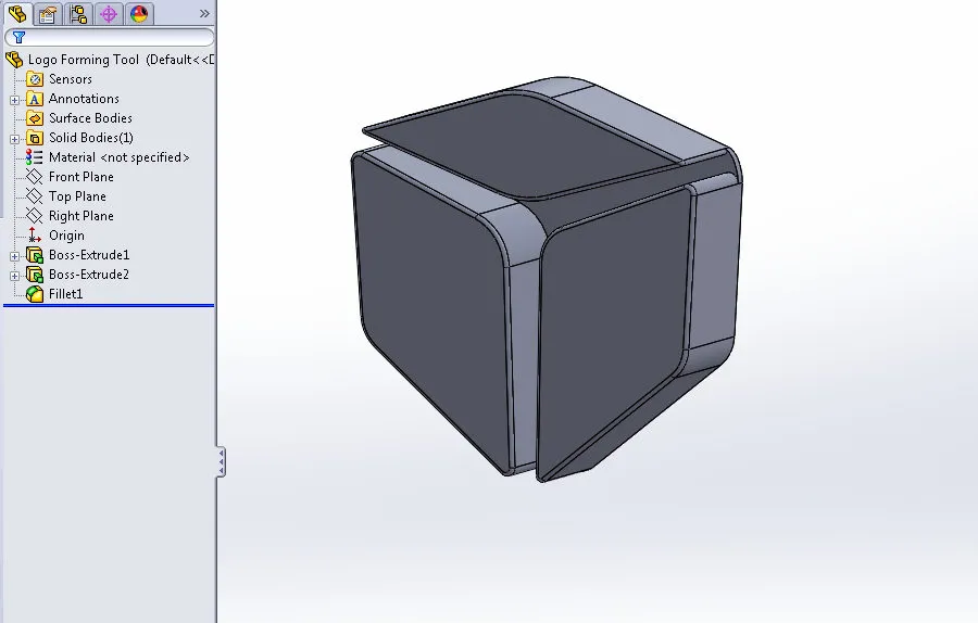
Multi-Body parts are not supported for sheet metal forming tools, so they will need to be bridged into a single body. I have also added fillets to the outer edges of the forming tool.
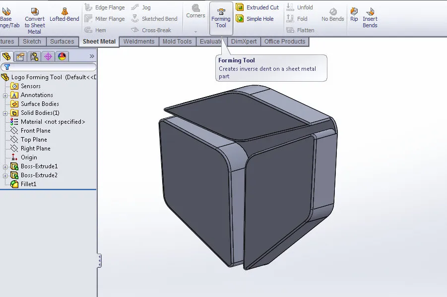
Once you have a single-bodied part that represents our form tool shape, select the Forming Tool option from the Sheet Metal toolbar. This will initiate Forming Tool feature creation. It can also be accessed from Insert > Sheet Metal > Forming Tool.
Forming Tool Feature
The first selection is the Stopping Face. This face dictates the depth to which the forming tool will be applied. Any faces in front of the stopping face will create the "form" in the sheet metal part.
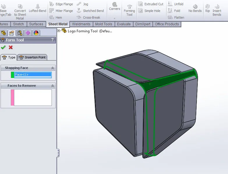
You can also choose Faces to Remove. The selected faces here will leave holes in the sheet metal part when the form tool is applied.
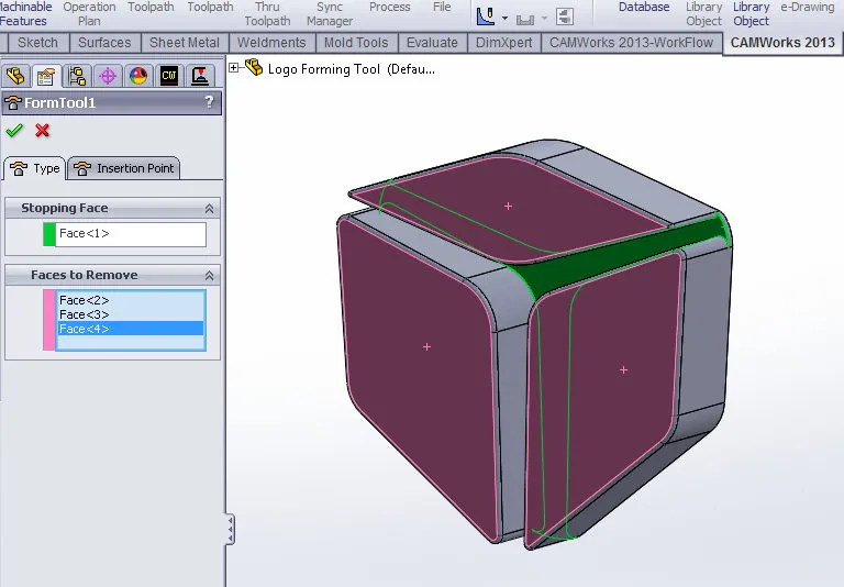
The next step is to choose the point by which we will place the tool on a sheet metal part. Click on the Insertion Point tab in the PropertyManager.
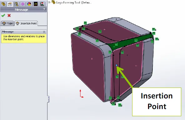
Insertion Points
Before continuing with this process, I want to take some time to explain the concept of insertion points. When placing a forming tool on a face of a sheet metal body, you are essentially placing a sketch point. This sketch point is related, in some way, to the shape of the forming tool and will dictate the location of that tool. This process is very similar to the placement of Hole Wizard features or creating a sketch for a sketch driven pattern.
After clicking on the tab, you will see that SOLIDWORKS has converted the edges of your stopping face to sketch geometry. It has also placed a point at the centroid of the form tool. This is your insertion point and if we do nothing, this will be its default location.
There are many methods by which to locate this insertion point, and I suggest figuring out the best method for your application. The main concept is that the point’s location should be fully defined if you do not want it to be the centroid of your forming tool.
In this tutorial, however, I will show my preferred method, which is to relate the insertion point to the sketch geometry of one of the previously created features. To do this, expand the FeatureManager Design Tree and show the sketch of the feature of interest, as seen below. Once the sketch has been shown, drag your insertion point onto a point of interest in the sketch.
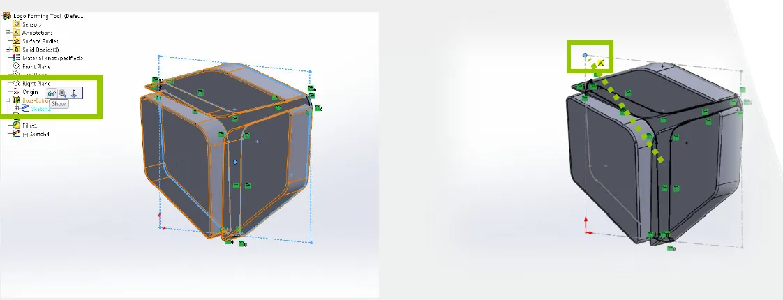
Showing Feature Sketch Dragging Placement Point
Note: In this case, I had created extra sketch geometry to allow dimensioning from the top-left corner of the forming tool during placement.
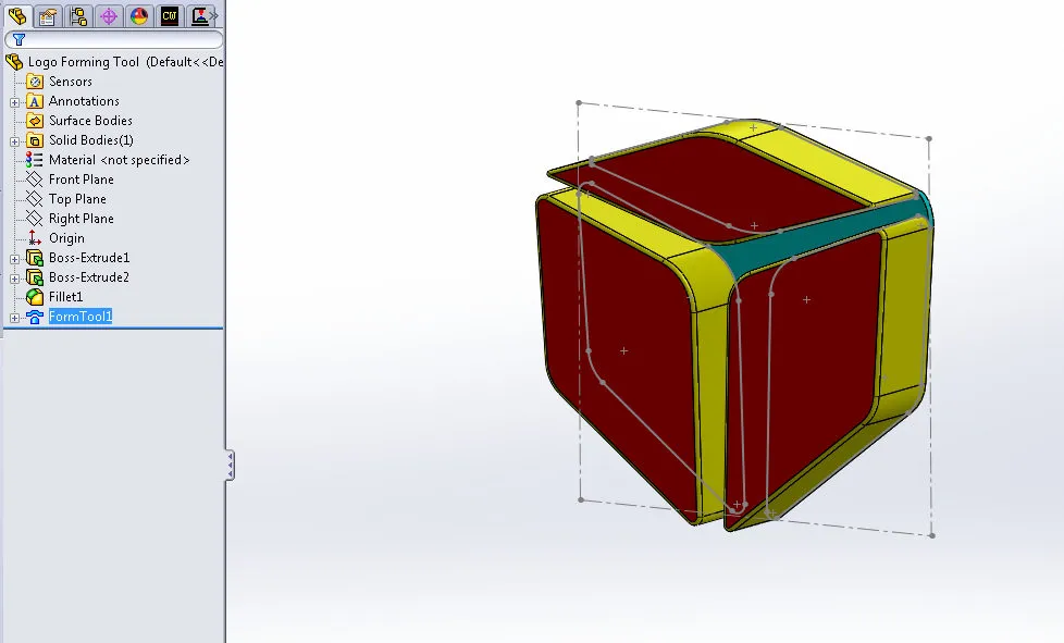
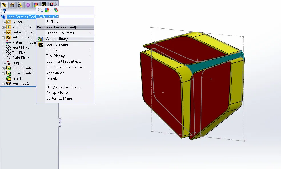
After clicking the green checkmark to accept the selection, the appearance of the part will be altered. The teal face represents the stopping face as selected during the form tool creation. The yellow faces represent the form that will be applied to your sheet metal parts.
At this point, the form tool has been successfully created. But how do we apply it to parts? Our next step is to add it to our Design Library for
easy access when designing sheet metal parts.
Adding Tool to Design Library
The design library is an area to store commonly used features, blocks, To add the forming tool, right-click on your part at the top of the feature tree and select Add to Library.
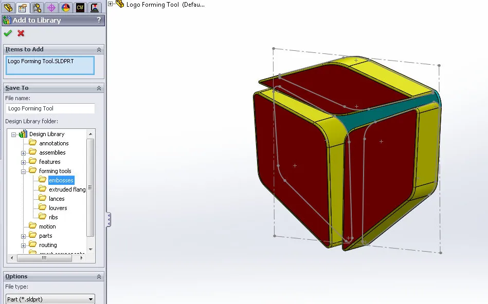
The Add to Library PropertyManager will appear on the left side of your screen, and you will get to choose the folder you want to place it in. I’ve chosen below to place it in the Embosses folder. It is important to put it inside of the Forming Tools folder for it to function correctly. You can also choose a File Name if you would like its name in the Design Library to be different than the name of the part file.
After clicking the green checkmark, you will be able to find your newly created forming tool in the design library. At this point, the forming tool can be dragged onto any flat sheet metal face (of sufficient size) and you will see your tool pressed into the sheet metal body.
![]()

Expand Your SOLIDWORKS Skillset
How to Copy SOLIDWORKS Custom Properties to Other Files
SOLIDWORKS - Weldment Configurations
![]()
About GoEngineer
GoEngineer delivers software, technology, and expertise that enable companies to unlock design innovation and deliver better products faster. With more than 40 years of experience and tens of thousands of customers in high tech, medical, machine design, energy and other industries, GoEngineer provides best-in-class design solutions from SOLIDWORKS CAD, Stratasys 3D printing, Creaform & Artec 3D scanning, CAMWorks, PLM, and more
Get our wide array of technical resources delivered right to your inbox.
Unsubscribe at any time.