3D PRINTING
ADDITIVE MANUFACTURING Solutions and Technology
 Now Serving US & Canada

Which 3D Printing Technology is Right For You?
-
-
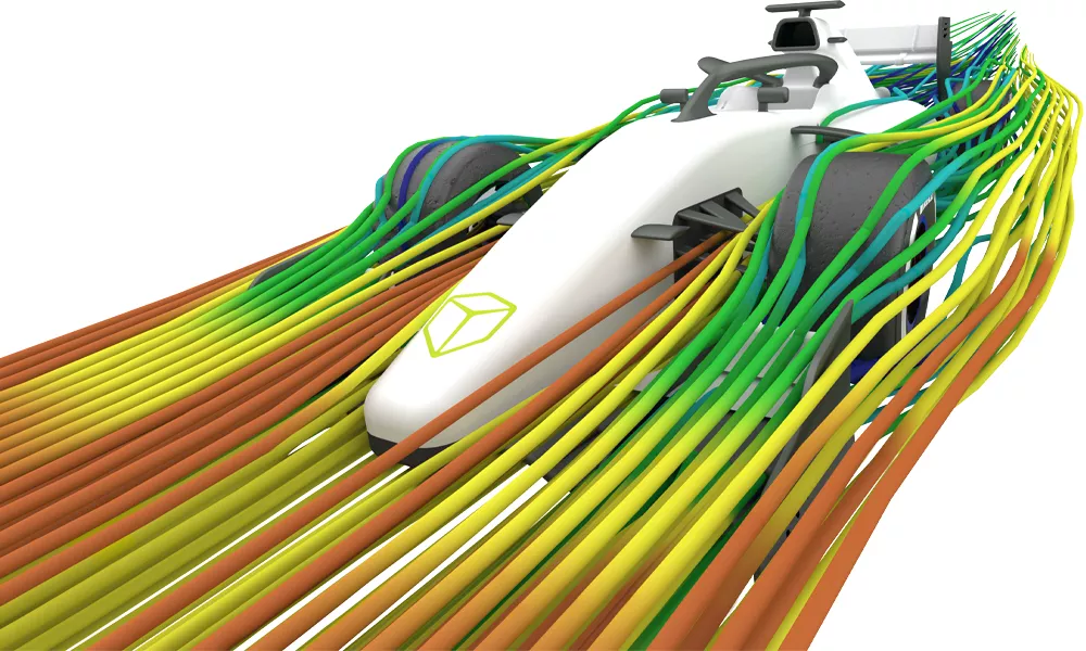
FDM
- Features:
- Durable Parts
- Large Build Envelopes
- Prototype and Test
- Uninterrupted Builds
-

-
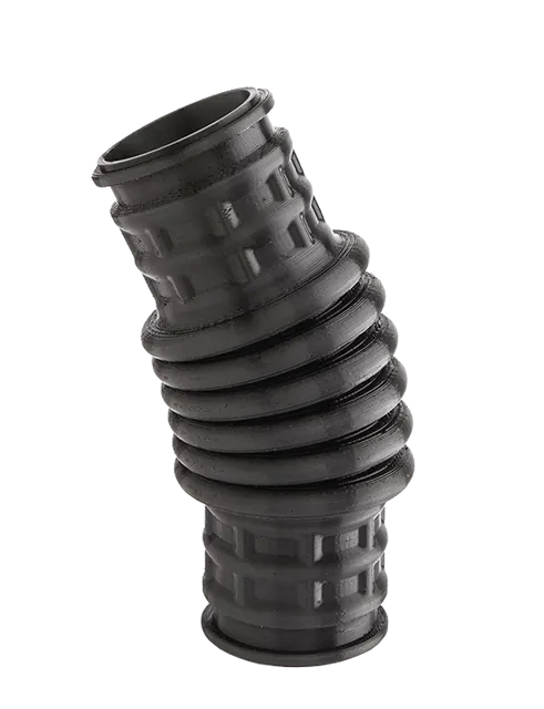
POLYJET
- Features:
- Realistic Models
- Multi-Material Prints
- Full-Color Pantone
- High Run Quantities
-
-
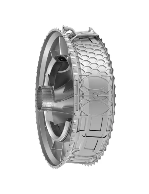
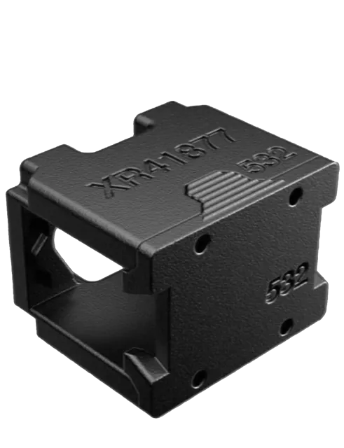
METAL
- Features:
- Multi-Laser Technology
- Support-Free Printing
- Multiple Metal Materials
- Integrated Powder Production -
-
-
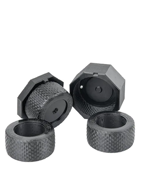
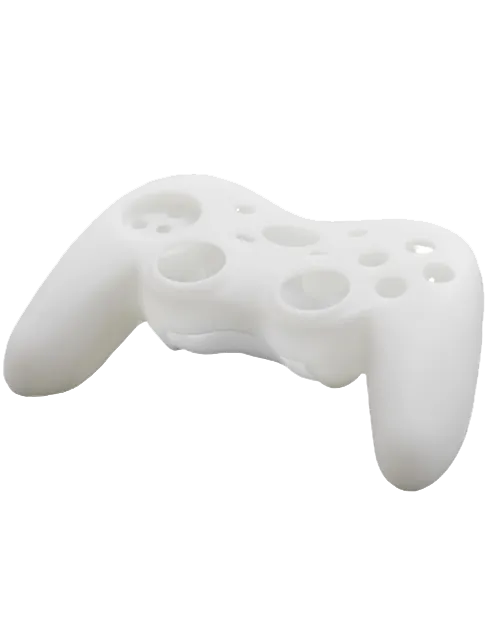
P3
- Features:
- Programmable PhotoPolymerization
- High Output Resin
- High Performance Materials
- Repeatability
-
-
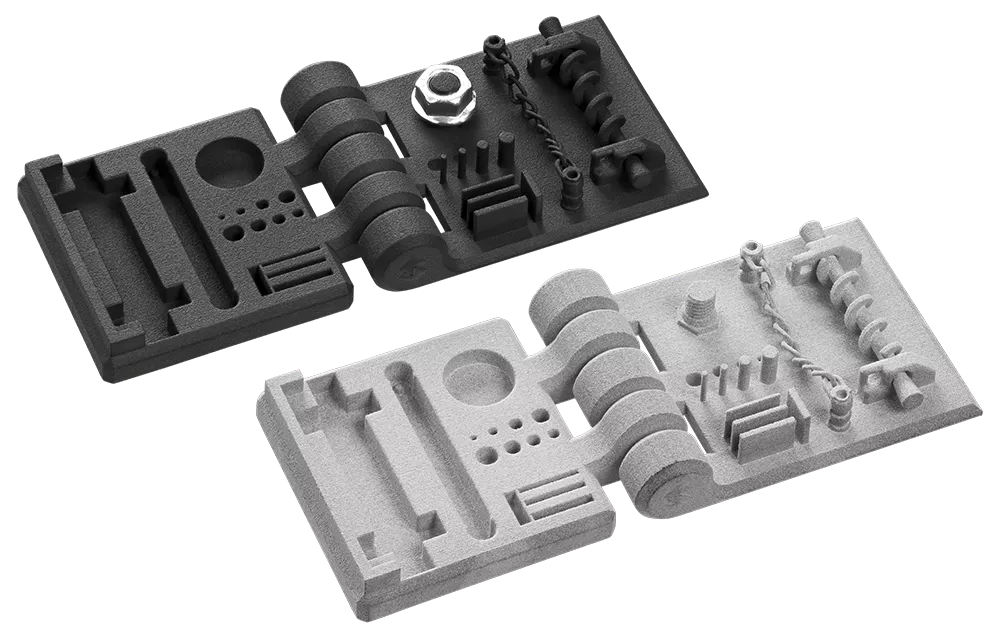
SAF
- Features:
- Selective Absorption Fusion
- High Demand Output
- Accuracy and Repeatability
- Cut Hidden Costs
-
-
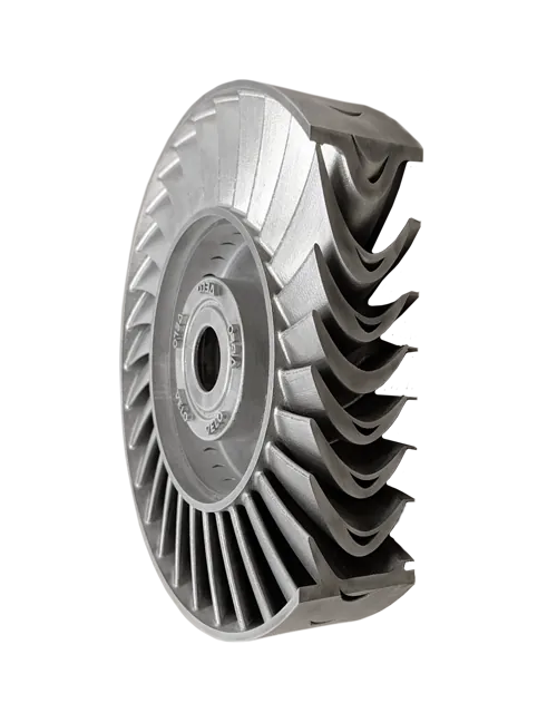
Stereolithography (SL)
- Features:
- Open-source Material Capability
- UV curing oven
- High Quality Parts
- 3-axis Dynamic Scanning
Need Custom 3D Printed Parts?
Transform your ideas into reality with precision and efficiency with GoEngineer's cutting-edge 3D printing services, delivering unparalleled quality and innovation.
and much more!
Which 3D Printing Technology is Right For You?
FDM
- Durable Parts
- Large Build Envelopes
- Prototype and Test
- Uninterrupted Builds
POLYJET
- Realistic Models
- Multi-Material Prints
- Full-Color Pantone
- High Run Quantities
METAL
- SupportFree
- Production Level Parts
- Multiple Metal Materials
- Print Low Angles
P3
- Programmable PhotoPolymerization
- High Output Resin
- High Performance Materials
- Repeatability
SAF
- Selective Absorption Fusion
- High Demand Output
- Accuracy and Repeatability
- Cut Hidden Costs
Stereolithography (SL)
- Open-source Material Capability
- UV curing oven
- High Quality Parts
- 3-axis Dynamic Scanning
DON'T MISS THese UPCOMING WEBINARs!
Leveraging Additive Manufacturing on the Factory Floor - Part 1
February 17, 2021, 11:00 AM - 12:00 PM, CDT
In this two-part webinar series, we talk about how 3D printing can help you produce more, increase the quality, and reduce the cost of your jigs, fixtures, and manufacturing aids. We will also discuss a few customer success stories, as well as the Stratasys printer and material portfolio.
Leveraging Additive Manufacturing on the Factory Floor - Part 2
February 24, 2021, 11:00 AM - 12:00 PM, CDT
In this two-part webinar series, we talk about how 3D printing can help you produce more, increase the quality, and reduce the cost of your jigs, fixtures, and manufacturing aids. We will also discuss a few customer success stories, as well as the Stratasys printer and material portfolio.
ADDITIONAL 3D Printing RESOURCES

AWARD-WINNING TECHNICAL SUPPORT
GoEngineer’s extensive technical knowledge can assist with your additive manufacturing needs. Our Award winning team is ready to help. Reach out and see why GoEngineer is the #1 reseller of SOLIDWORKS and Stratasys systems in the world!
3D Printing Courses
Learn to utilize all features and tools of Stratasys commercial 3D printers with GoEngineer additive manufacturing on-boarding training and 3D printing courses. Take advantage of our 3D printing team of experts to help launch all your 3D printing capabilities.

3D PrintING SERVICES
No matter the size, quantity, or complexity of part(s) needed, GoEngineer can help you! Take advantage of our 3D Printing Services to help your organization produce the best parts and prototypes available on the market.
Additional Resources
Take Advantage of GoEngineer’s Extensive Knowledge Base and Resources

Find a Solution
Our robust Knowledge Base contains over 12,000 resources to help answer your product design questions. From basic CAD questions to in-depth guides and tutorials, find your solution here. Find a Solution
PROFESSIONAL TRAINING
Improve your skills with professional training and certifications in SOLIDWORKS, CAM, 3D Printing, and 3D Scanning offered four ways: self-paced, online, on-site, or in-classroom. Certified Training Courses

BLOG
#1 Technical Resource Worldwide - Right at your fingertips. Search or browse through hundreds of SOLIDWORKS tips & tricks, additive manufacturing product developments, announcements, how-to guides, and tutorials. Blog
YouTube Channel
Our YouTube channel hosts hundreds of educational tutorials, product demonstrations, recorded webinars, and best practices for all of our products and services. GoEngineer's YouTube Channel
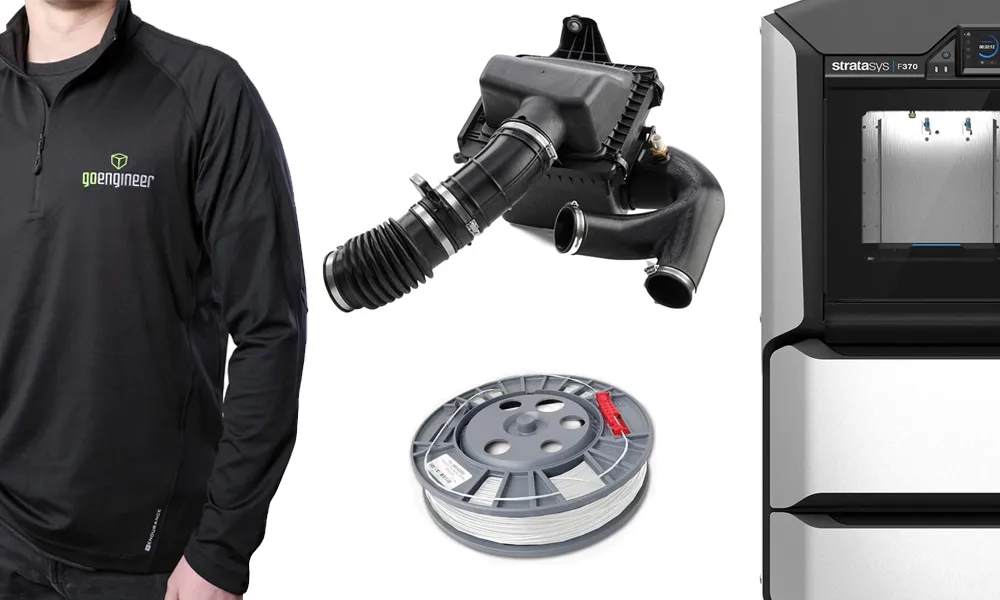
ONLINE STORE
Order 3D printing materials and consumables, enroll in SOLIDWORKS training classes, and buy official GoEngineer gear directly from our online store. Online Store
WEBINARS
Our engineering webinars are hosted by some of the top experts in the industry. They are always recorded, always free, and always offer a live Q&A. WEBINARS
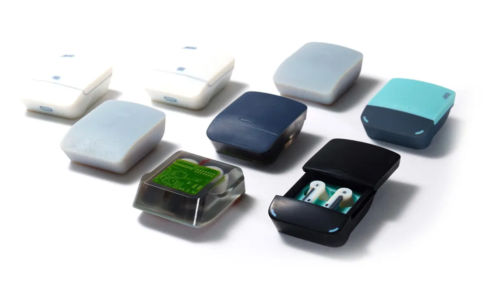
3D Printing Services
Need to 3D print a part? Our Additive Manufacturing experts will 3D print your part and deliver it to you using the latest technology on one of our professional FDM, PolyJet and SL 3D printers. 3D Printing Services