How to Make a Cube in SOLIDWORKS
Ah, the cube. It’s such a fundamental geometric shape that SOLIDWORKS decided to incorporate it as part of its own logo. It might not be the most exciting shape to create, but everyone has to start somewhere, right? And besides, it doesn’t have to be boring, right? ‘Right’ – on both counts! In this blog post, we’ll go through the most straightforward way to make a cube in SOLIDWORKS. Then, I’ll show you some other ways to make and manipulate cubes. One or two of these ways might seem silly, and that’s OK. The goal is to expose you to different ways of doing the same thing, in an ultimate effort to expand your SOLIDWORKS toolkit. Let’s get started.
Sketch a square, extrude it using Boss Extrude
This is probably the method you’re naturally going to pursue 9 times out of 10. This method results in a fully solid cube shape.
The basic steps, as shown, are:
- Select a plane or planar face and begin a sketch.
- Select the rectangle tool. In this example, toggle to the Center Rectangle option.
- Make your first click on the red origin icon. Make your second click wherever you’d like while trying to approximate a square shape.
- Add a dimension to one of the lines on the square’s perimeter. Then, select this line and another line (while holding the Ctrl key). Add an “Equal” relation between the lines.
- Extrude the square using Boss Extrude. Use the ‘Mid-plane’ end condition for the extrusion. Type in the same depth for the extrusion as you used for the dimension in Step 4. Select the green check when finished.
Make a thin feature extrusion from your sketched square
Of course, not all cubes are meant to be fully solid. Some are meant to be hollow. There are plenty of examples of this. One everyday example is a holder piece for common household blinds.
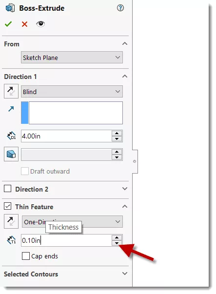
If you do find yourself needing to model such a shape, you can follow method A almost exactly as it is listed. The only difference is that you’ll specify one additional option during step 5.
During step 5, be sure to select ‘Thin feature.’ This tells the Boss Extrude feature you want a thin-walled extrusion. That’s right – it’s that easy! Just one checkbox.
Take method 1 and make it hollow!
You could just ignore method B altogether and achieve the same end result. Again, there are multiple ways to do almost anything in SOLIDWORKS. This is another way to achieve the same end result as method B.
Follow method A exactly as it’s described. After hitting the green check, go to the Features tab on your CommandManager ribbon, and select the Shell feature.
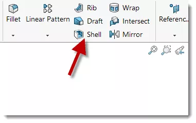
Using Shell, you can specify the resultant thickness of your part post-execution. You also have the option to specify faces for removal, but you don’t have to if you don’t want to.
If you use the Shell command on a standard cube, you probably won’t be able to tell it’s a thin-walled part, naturally, unless you look inside of it. Consider using the section view tool to see its newly-hollowed insides.
Let’s get goofy and use Intersect… with zero sketches!
This is, admittedly, the most impractical method of creating a cube. Part of the goal of this article is to open your eyes to different problem-solving approaches when modeling. This one’s pretty outside the box, and it calls upon a different tool: Intersect.
Intersect, which came out in SOLIDWORKS 2013, gives us the ability to create a solid using an intersecting mixture of solids, surfaces, and/or reference planes. As the name infers, you can extract bodies from the intersection of any number of these entity types.
As such, we can create a cube using the intersection of reference planes – without the need to sketch anything at the part file level! This may not be the most productive way of making a cube, but it will undoubtedly impress some of your SOLIDWORKS power user friends and mentors.
A rule of thumb in SOLIDWORKS design is to try to go with the modeling approach that is quick to implement, correctly detailed, and easy to potentially edit or modify. You’ll find that different modeling challenges will require different solutions if we’re to abide by these guidelines on an ongoing basis!
Professional SOLIDWORKS Training from GoEngineer
Learn more about the essential modeling techniques in SOLIDWORKS in our SOLIDWORKS Essentials training courses. These courses are offered in person, live over the web, or on-demand.
![]()
About GoEngineer
GoEngineer delivers software, technology, and expertise that enable companies to unlock design innovation and deliver better products faster. With more than 40 years of experience and tens of thousands of customers in high tech, medical, machine design, energy and other industries, GoEngineer provides best-in-class design solutions from SOLIDWORKS CAD, Stratasys 3D printing, Creaform & Artec 3D scanning, CAMWorks, PLM, and more
Get our wide array of technical resources delivered right to your inbox.
Unsubscribe at any time.