SOLIDWORKS Weldment Profiles & Weldment Tools Guide
The SOLIDWORKS Weldments tool can be used to create 3D structures using components with multiple profiles with a variety of end-conditions, within a single multi-body Part File. Since any closed profile can be used, this tool is not limited to welded metal applications. Weldments can be used for anything from machine frames and railings to picnic tables and garden sheds. In this guide, we'll cover the basics of creating a weldment design in SOLIDWORKS, weldment profiles, and weldment tools.
- Suggested Reading >> SOLIDWORKS at Home: DIY CAD Projects
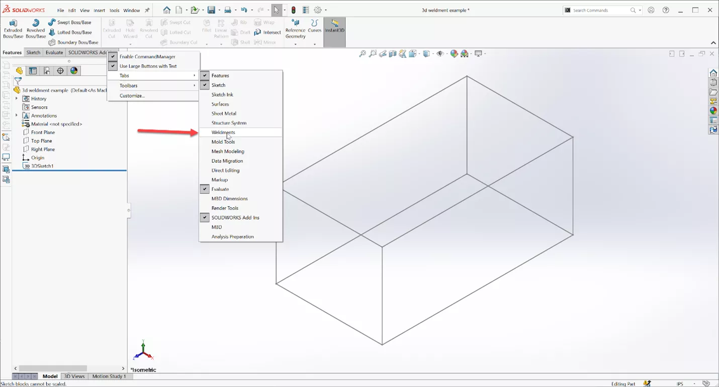
Inside SOLIDWORKS, I have drawn a wireframe box. The sketch in this example, 3DSketch1, is a three-dimensional sketch. If you are unfamiliar with 3D Sketches, you can also use two-dimensional sketches on multiple planes. Any wireframe sketch method you use to create the desired design will work.
Add SOLIDWORKS Weldment Tab to CommandManager
Adding the Weldment tab to the CommandManager provides faster access to create 3D sketches, add and trim weldment members, and add gussets and weld beads. To do so, right-click on the Tabs area in the CommandManager to access this menu and select Weldments.
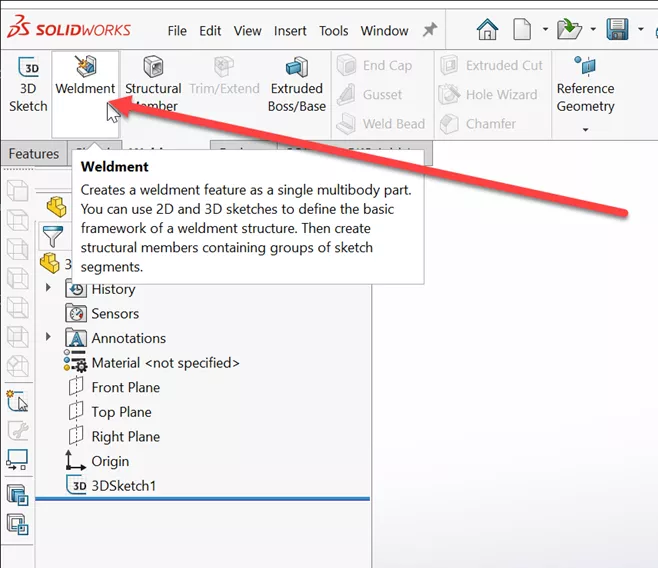
Now that the Weldment tab is added to the CommandManager, we can turn this into a weldment and start adding the structural members.
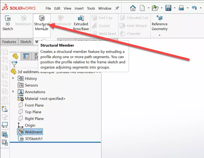
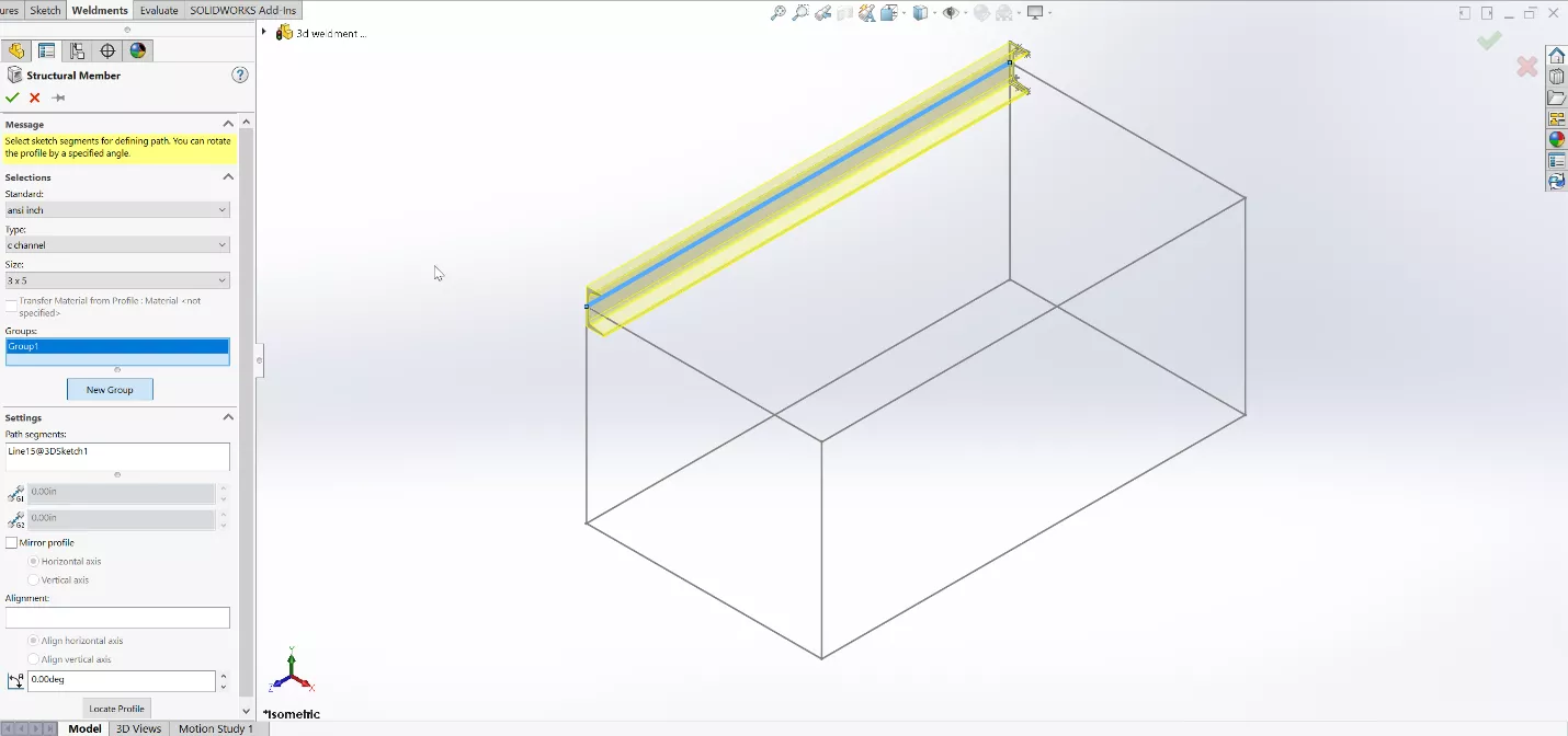
Inside the Structural Member command, select the Standard, Type, and Size to add members to the previously created sketch.
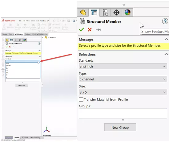
Once the profile and size are chosen, select the sketch entity you would like the member to follow.
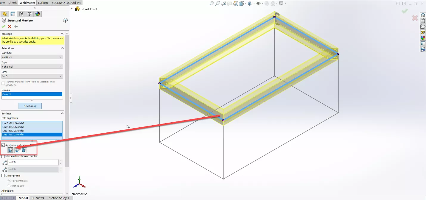
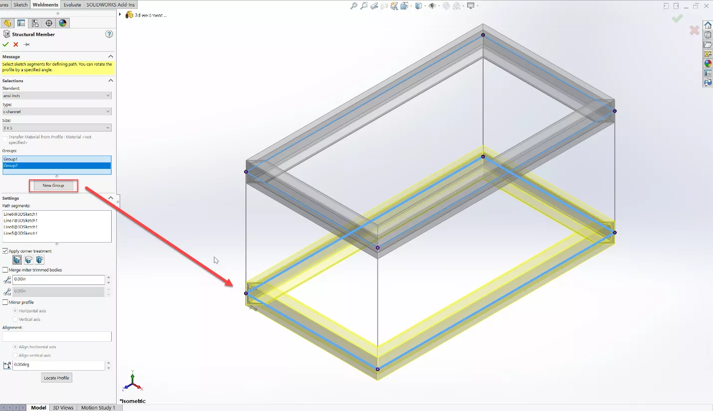
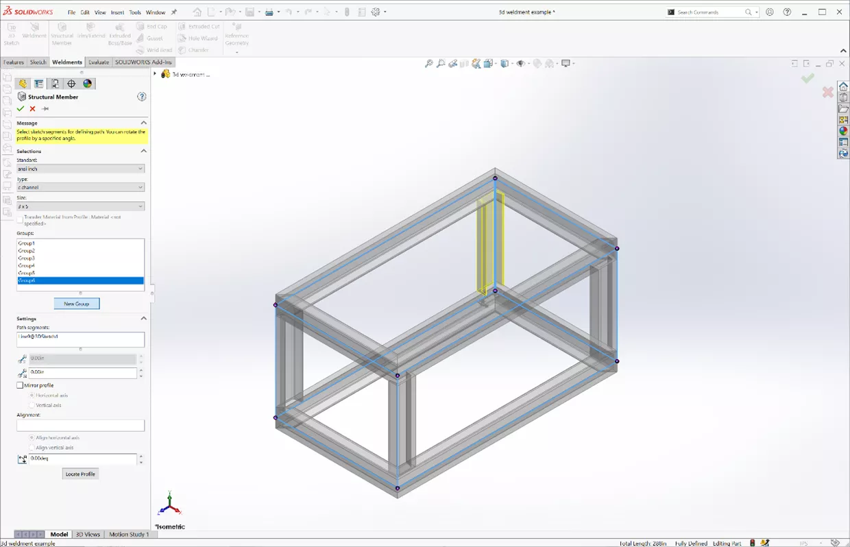
When adding structural members, SOLIDWORKS groups them automatically. Groups of Structural Members must be a continuous selection path or parallel lines. In this example, we will group the top members and then edit their connection conditions to meet the desired corner treatment (mitered, in this case). Add another group for the bottom members as below.
The vertical weldment profiles cannot be grouped with either of the existing groups because they are not all part of a continuous selection path. Instead, each vertical leg will need to be added to its own individual group, since each will need to be rotated/mirrored and relocated to have the correct placement of the profile.
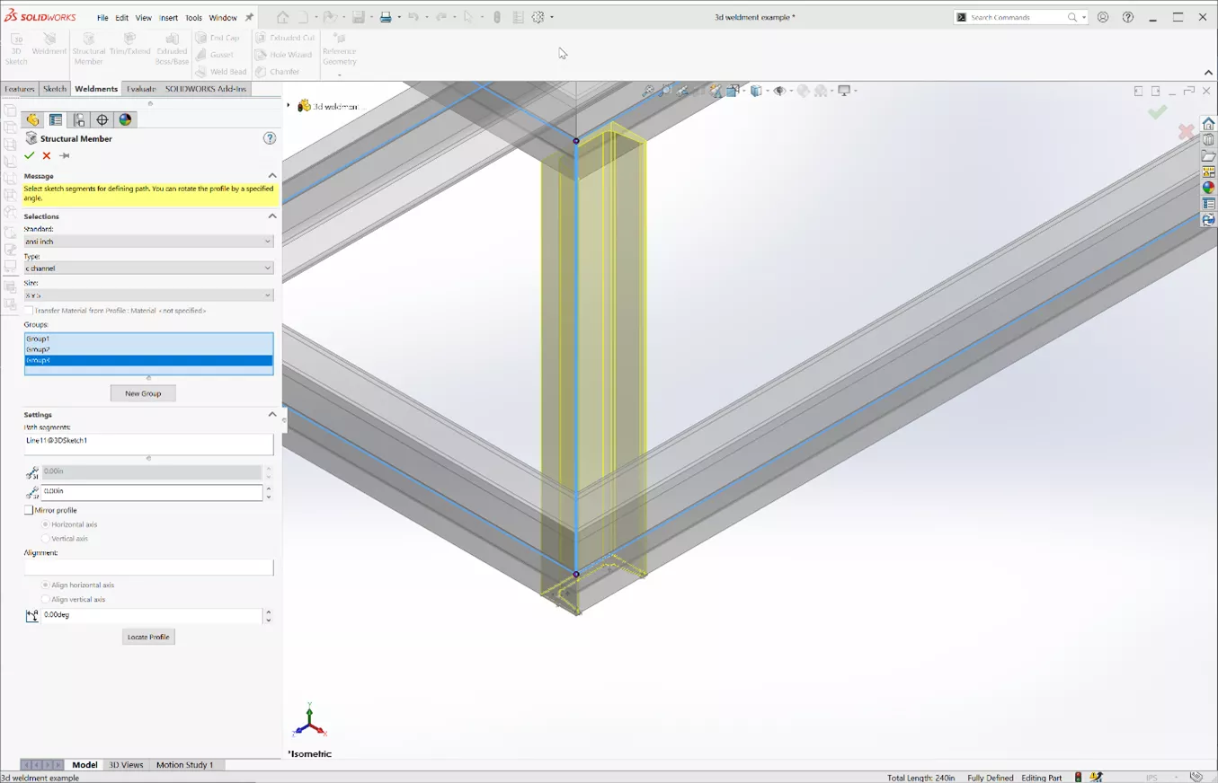
In this case, the default orientation is not correct in the above screenshot. Use the Locate Profile button to re-locate the profile sketch and use mirror and vertical axis to help invert the profile and position it. The option of rotating at a specific angle could be used in this situation as well.
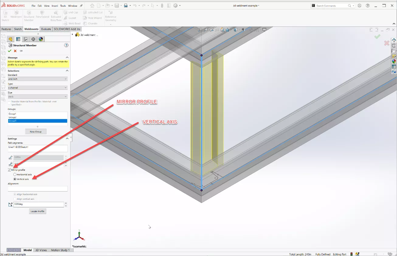
In this case, the default orientation is not correct in the above screenshot. Use the Locate Profile button to re-locate the profile sketch and "use mirror" and "vertical axis" to help invert the profile and position it. The option of rotating at a specific angle could be used in this situation as well.
Trim/Extend Command
Now that we have covered the basics of adding structural members, let’s look at the Trim/Extend command.
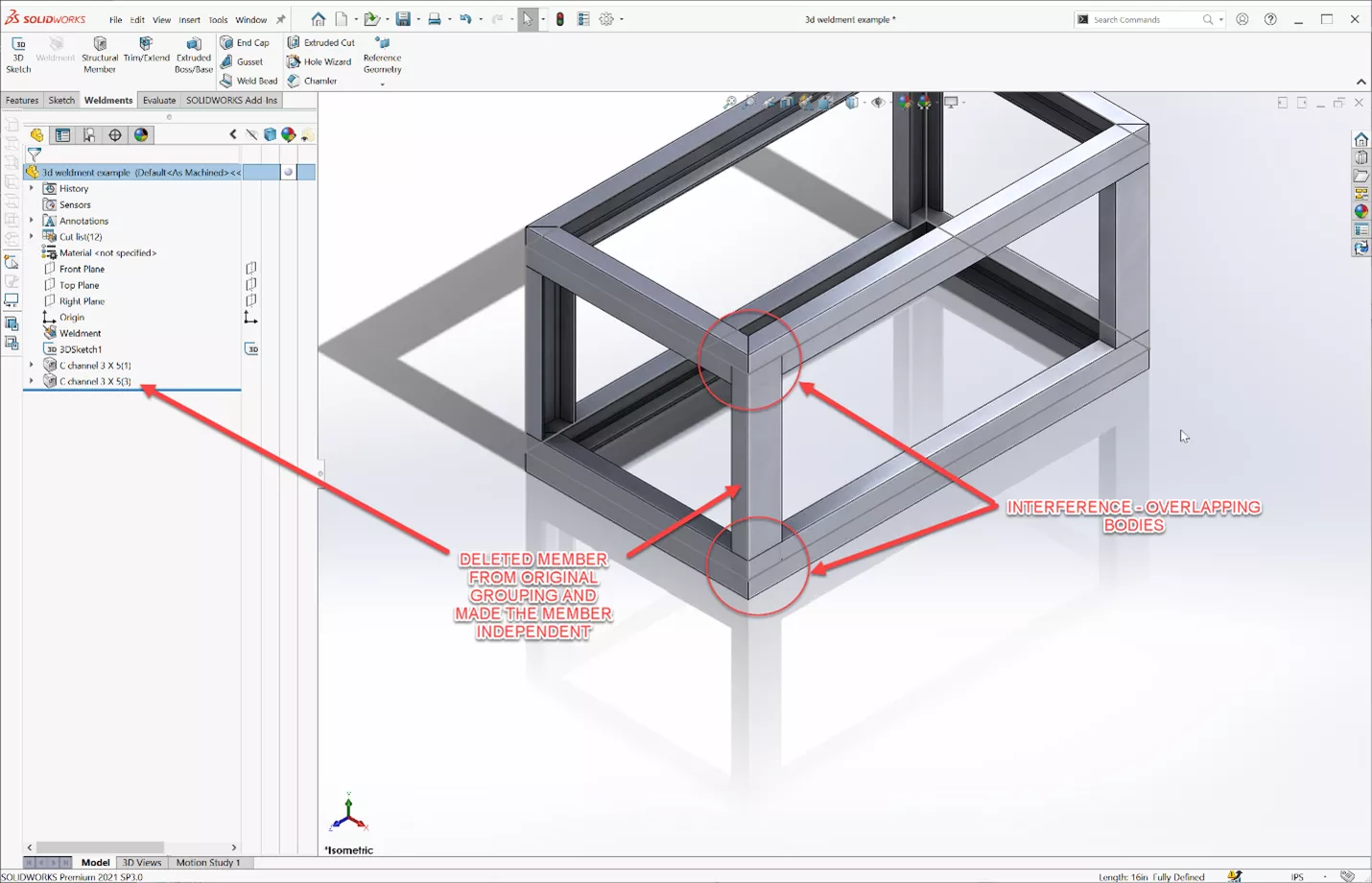
In this example, I have removed one of the vertical members, then added the member back into the model as a separate feature.
I have selected the Weldment Trim/Extend command, with the vertical member selected as the body to be trimmed and the horizontal members as the boundaries or end conditions. We can choose a body or use a face/plane to define the trimming boundary. In this example, either one will produce the same results.
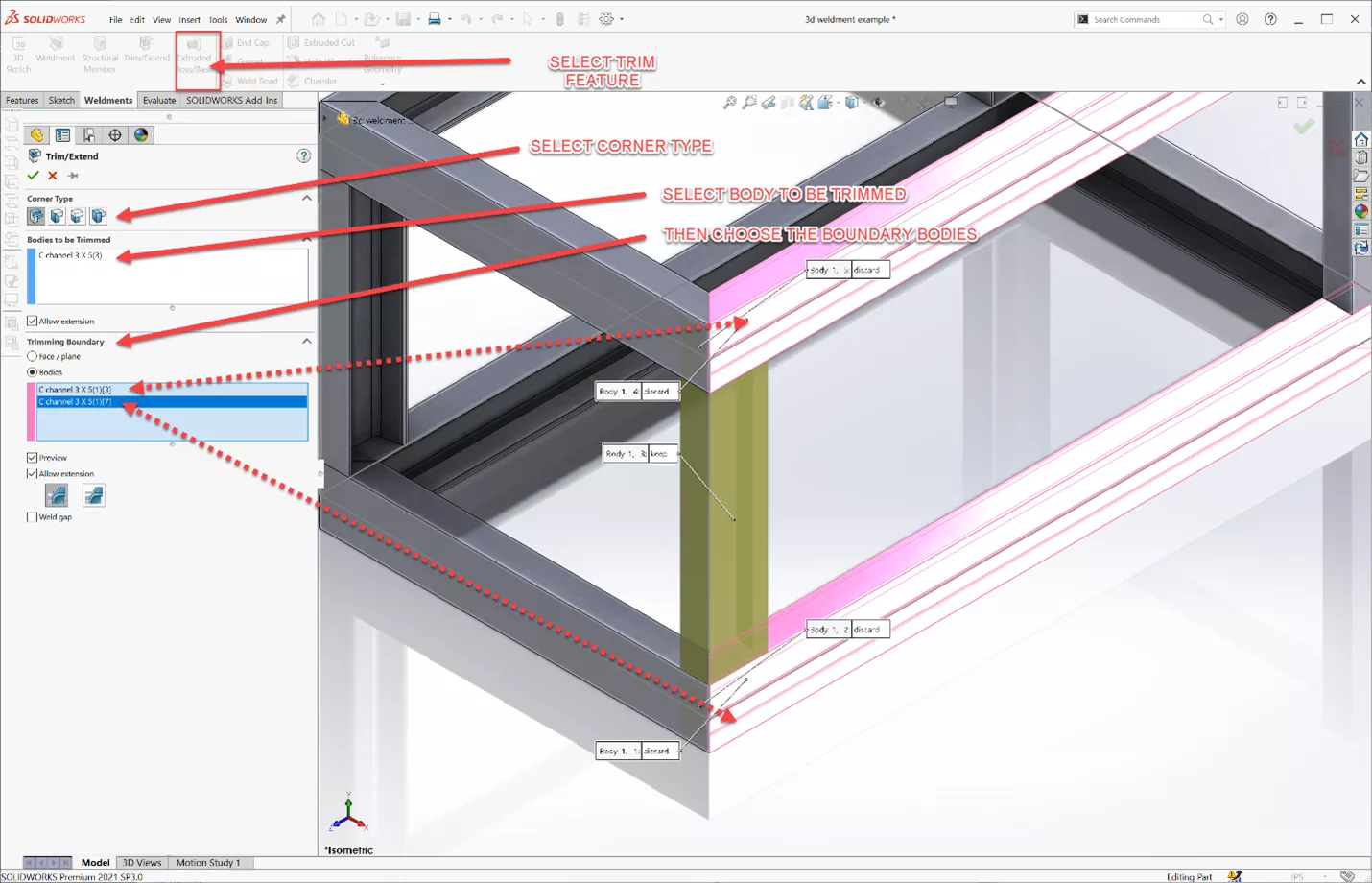
The difference between these two selections is a plane will share the end condition up to the flat face of the plane, where a body can be set to match the contour of a surface that is not flat.
Choosing the top face of the member (highlighted in the image above), little popups appear. A single click will toggle which to keep or discard.
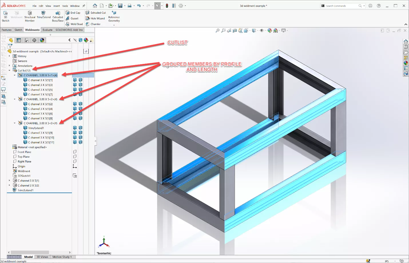
In the FeatureManager design tree is a Cut List folder for the structural members in this weldment. This Cut List contains all the information we need to represent a weldment BOM (Bill of Materials), which can be used on a drawing to show the common structural members and lengths.
Right-click on the folder and set the update option to manually update the Cut List (Automatic updates lets SOLIDWORKS update the Cut List whenever changes are made).
Additional Tips
- Lines and arcs can be used for a wireframe but not splines.
- Custom weldment profiles can be added or imported to the weldment library. Check this article: Adding Weldment Profile Packs from SOLIDWORKS Content.
- [VIDEO] Get Weld Soon (Welding Enhancements and Tips)
SOLIDWORKS Weldment Training
Learn to build stand-alone sheet metal parts and create standard structural members by enrolling in Sheet Metal & Weldments training with GoEngineer.

SOLIDWORKS CAD Cheat Sheet
Our SOLIDWORKS CAD Cheat Sheet, featuring over 90 tips and tricks, will help speed up your process.
More SOLIDWORKS Weldments Tutorials
SOLIDWORKS - Weldment Configurations
SOLIDWORKS 2020 Structure Systems for Weldments

About Matthew Kusz
Matthew Kusz is a Senior Technical Support Engineer at GoEngineer. When Matthew isn’t assisting customers with their engineering challenges, he spends his free time repairing antique watches/clocks, designing furniture, tending his aquariums and learning about bee keeping.
Get our wide array of technical resources delivered right to your inbox.
Unsubscribe at any time.