Creating Reference Planes in SOLIDWORKS: Offset, Angle, Mid, & Cylindrical Surface
In this tutorial, we explain how to create four different reference planes in SOLIDWORKS:
- Offset Planes
- Angle Planes
- Mid Planes
- Cylindrical Surface Planes
Offset Planes
The most common type of reference plane is an offset plane. To create an offset plane, select the Reference Geometry drop down on the CommandManager and choose the Plane option.

Once the option to create a plane is open, select a face or another plane and set a distance for the offset. (Figure 1 & 2) There is also the option to create multiple planes when making an offset plane (Figure 3). When creating multiple planes this way, all of the planes created will have the same offset from each other.
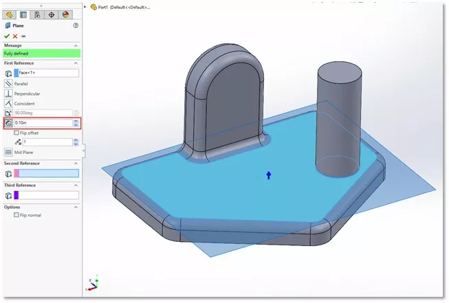
(Figure 1)
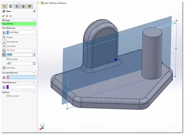
(Figure 2)
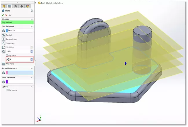
(Figure 3)
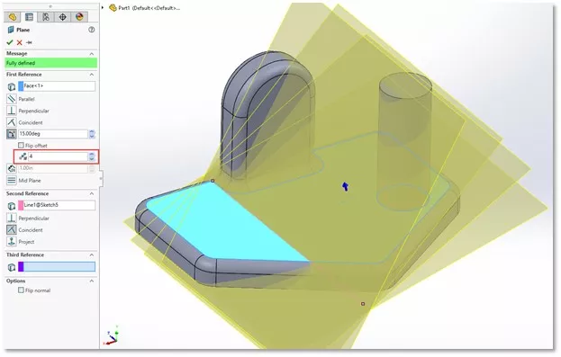
Angle Planes
To create an angle plane, you’ll need a face and an axis line to angle about.
The axis line can be a model edge or a sketch line. (Figure 4) By default, the angle of the new plane will be perpendicular to the selected face/plane but you can change the angle at which the plane is offset from the selected face.
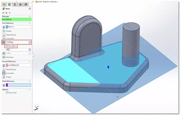
(Figure 4)
Multiple angle planes can be created at the same time; each being offset from the next by the selected angle. (Figure 5)
(Figure 5)
Mid Planes
When two faces are selected, a mid plane is created by default. The selected faces are not required to be parallel (Figure 6). If they are parallel, the resulting plane will be parallel and halfway between them. If not, the plane will be positioned between the two faces. A common use of this type of plane would be to create a mirror plane in the center of the part.
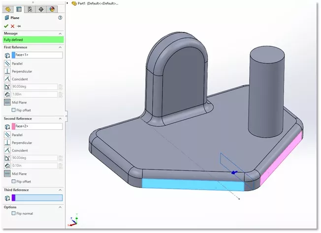
(Figure 6)
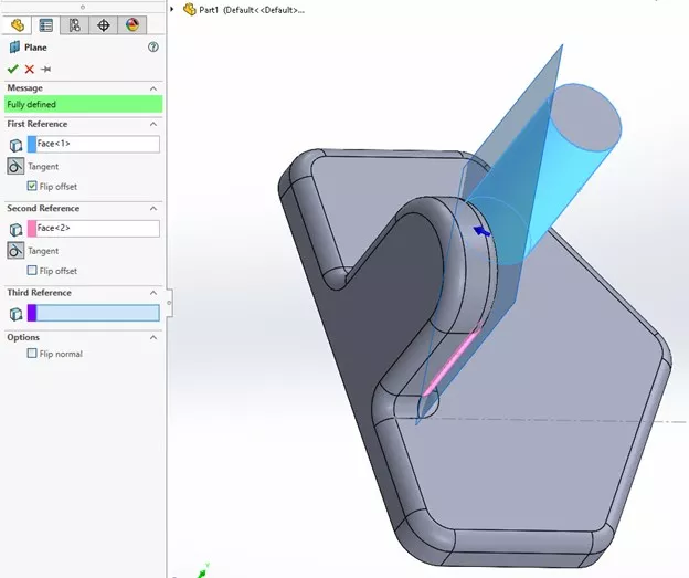
Cylindrical Surface Planes
Planes on cylindrical surfaces can get confusing because they often need more selections in order to finalize the plane. For example, if a cylinder and a plane are selected, the plane will rotate about the cylindrical face as the angle is adjusted. (Figure 7) Or, if multiple cylindrical faces are selected, a plane will be added that is tangent to both.
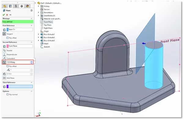
(Figure 7)
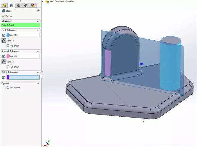
(Figure 8)
(Figure 9)
In either case, selecting the Flip option will let you set which side of the respective cylinder is used as the reference. (Figure 8 & 9)

SOLIDWORKS CAD Cheat Sheet
Our SOLIDWORKS CAD Cheat Sheet, featuring over 90 tips and tricks, will help speed up your process.
I hope you found this article helpful. To learn more about SOLIDWORKS, check out more tips and tricks below.
More SOLIDWORKS Tutorials
Smart Explode Lines in SOLIDWORKS Explained
2 Ways to Reference a Cross-Section in SOLIDWORKS
Creating and Adding Weld Beads in SOLIDWORKS Models & Drawings
Record a Basic SOLIDWORKS Macro
About Nick Stanley
Nick Stanley is a SOLIDWORKS Technical Support Specialist at GoEngineer.
Get our wide array of technical resources delivered right to your inbox.
Unsubscribe at any time.