Convert 2D DWG Data into a 3D SOLIDWORKS Part File

There are many ways to convert DWG files into SOLIDWORKS, but I’ll show you my favorite.
I’ve shown this in a number of my training classes over the years, but I thought it was about time to put it into a blog.
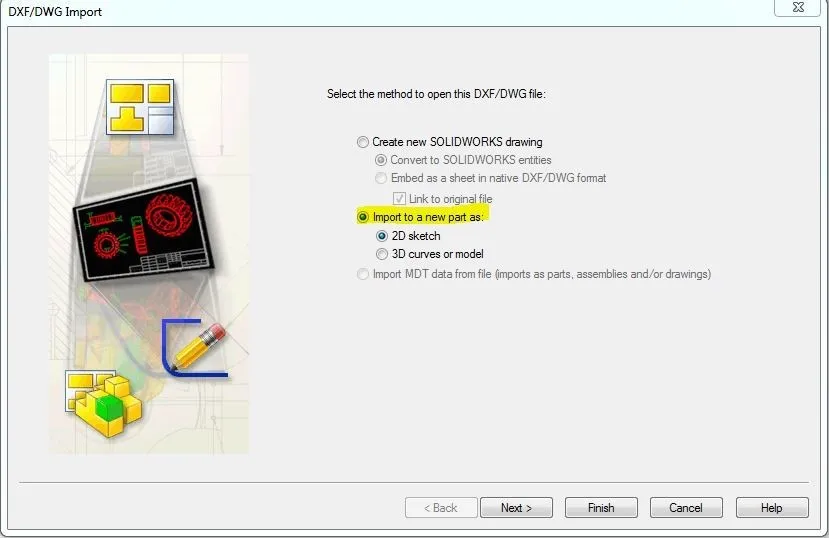
Open the file in SOLIDWORKS, and select the DWG or DXF file. Make sure you choose Import to a new part:
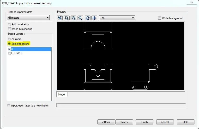
If the data is clean, you can use it as is, but if there are many unwanted layers you can choose not to import them:
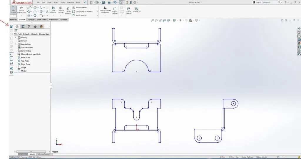
Click finish and it will bring in all 3 views into one plane in SOLIDWORKS. You’ll need to use the 2D to 3D toolbar, box select the lines that represent each view and click on the relative view button:
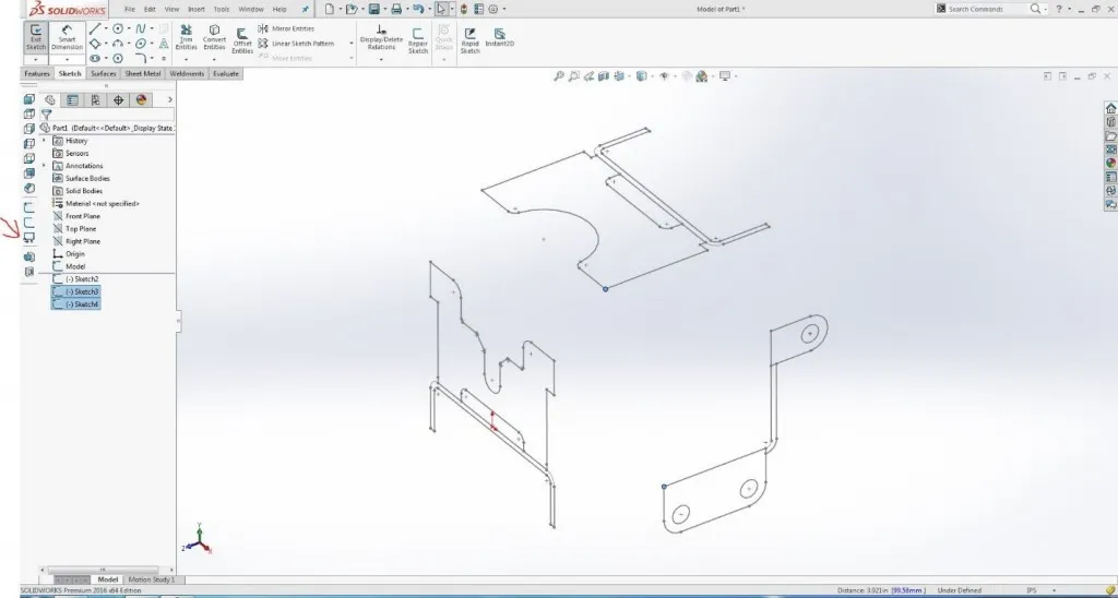
This will line up the Front and Top, and the Front and Right, but not the Top and Right. CTRL-select a couple sharp corners and click on the Align Sketch button:
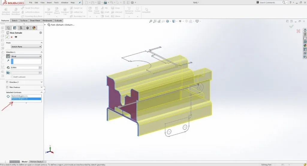
This will get the 3 views into the correct orientation and location on the correct plane. Next, you’ll extrude using the contour selection tool to extrude the areas where there will be material:
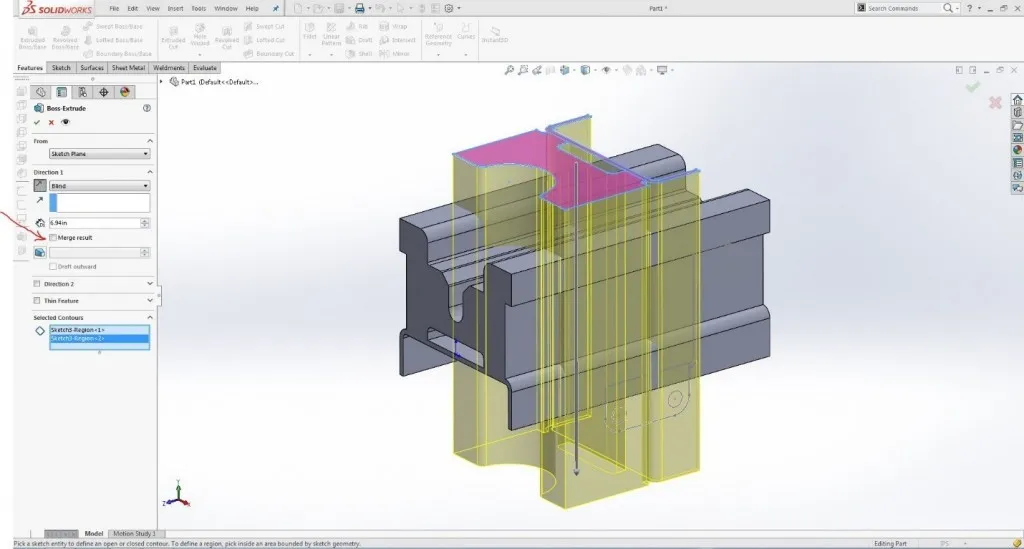
Next, reorder the tree so the extrude is before the other two sketches, and repeat the extrusion process with the Top and Right view, clearing the merge result check box:
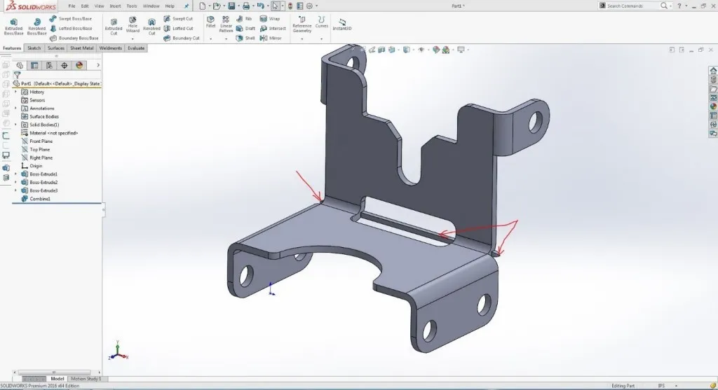
This will result in a jumbled mess of 3 bodies. However, you can use a handy tool under Insert – Features, called Combine. Be sure to set this tool to the common option, which will leave geometry where the 3 bodies intersect:
Insta-Part! With the possibility of some artifacts from the overlap, simply delete these using cut-extrude or delete face:
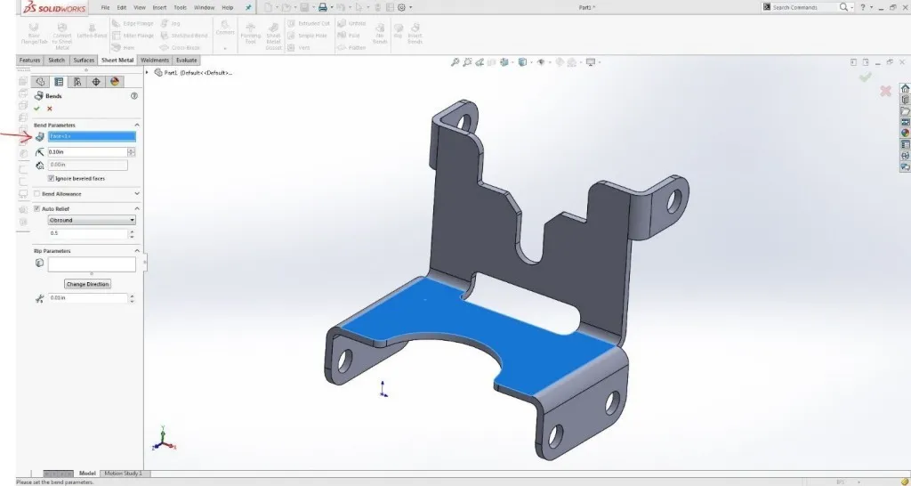
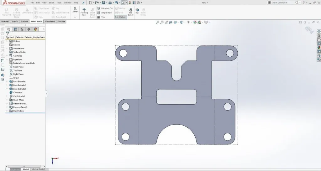
If you’re importing a sheet metal part, you can use Insert Bends and choose a fixed face:
And then, with your K Factor or Bend Allowance set, you can get a flat blank by clicking flatten in the sheet metal command manager:
This is a very quick way to translate DWG data into SOLIDWORKS parts. Of course, there are a couple disclaimers:
- These instructions assume the DWG was correct to start with.
- I did not include a step of fully defining the sketch entities, which would be necessary for editing the data if needed.
This does not work with every geometry condition, but when it does its pretty slick.

About John MacArthur
John MacArthur is an Elite AE and the Engineering Manager - MidWest for GoEngineer. John’s hobbies and interests focus around designing and building cool things. He enjoys building and wheeling off-road machines, has an 80 lb. Pitbull named Thor, and likes to take broken things and return them to fully functional items.
Get our wide array of technical resources delivered right to your inbox.
Unsubscribe at any time.