Customizing the SOLIDWORKS Hole Callout File
A common question I receive is, "How do I get SOLIDWORKS to call out holes the way the shop floor wants them?" Let’s begin by clearly defining how SOLIDWORKS hole callouts work.
When you click on the Hole Callout button in a SOLIDWORKS drawing, it does a lookup to the file location in tools, options, document properties Hole Callout Format File. SOLIDWORKS is hardcoded to look for a file named calloutformat.txt in this location.
It then reads the calloutformat.txt file for information on how to callout the hole based on information in the hole wizard feature. Specifically, by standard, hole type, end condition, and options.
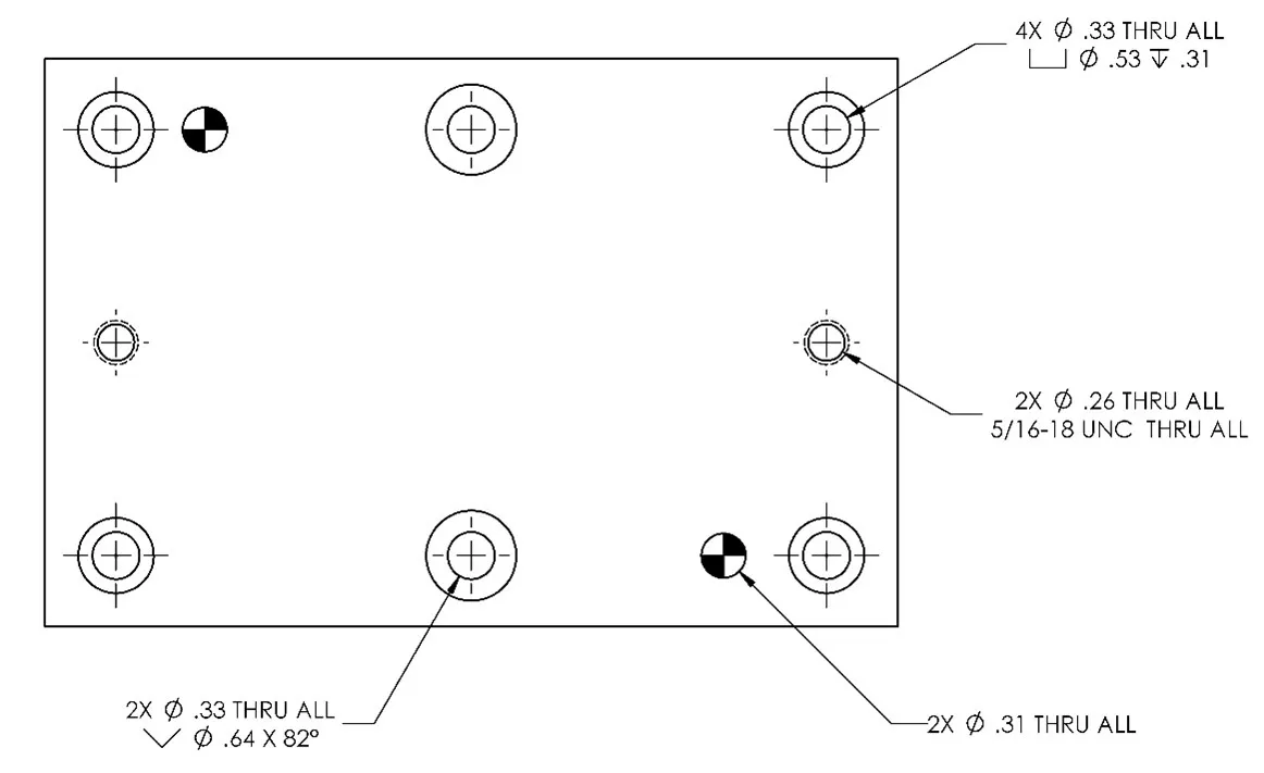
The SOLIDWORKS default Hole Callout calls out holes with all the detail needed to machine the hole:
So, why would I want to change it?
Well, the simple answer is: machinists can be quite particular on how they want holes called out. And frankly, for good reason. These callouts often dictate tools used, tolerance, etc.
A common request I receive is from customers with an in-house toolroom wanting the callouts to say:
Drill & C’Bore for 5/16 SHCS
Drill & C’Sink for 5/16 FLHS
Drill & Tap for 5/16-18
Drill & Ream for P.F. 5/16 DWL
So, I’ll use this request as an example of how to customize the Hole Callout Format file to get the above results.

Customizing Hole Callout File
The first step in customizing the hole callout file is making a backup of the default one.
Browse to the location specified in File Locations, the default location is:
C:\Program Files\SOLIDWORKS Corp\SOLIDWORKS\lang\english
Make a copy of calloutformat.txt and rename it calloutformat-default.txt
Now that we have a copy, open calloutformat.txt in notepad. Depending on your computer settings, you may need to run notepad as an administrator to get write access to this file. This is a rather large, and seemingly daunting text file. We’ll be focusing on two specific areas to customize it.
The first area we’ll want to check out is the end of the document, at the list of available variables. These are surrounded by < >. To accomplish the example listed earlier we’ll need <hw-fstsze> (fastener Size) , <hw-threaddesc > (thread description), and optionally <hw-fsttyp> (fastener type)
The second area we’ll be focusing on is the individual holes in the standards areas. Specifically, for this article, I’ll be showing how to customize the ANSI Inch standard, which is up at the top of the text file.
Customizing Counterbored Holes
Under the counterbored holes header, you’ll see all the options. We’ll modify the *Thru Hole callout:
COUNTERBORE-THRU=<MOD-DIAM> <hw-thruholedia> <hw-thru>;\
<HOLE-SPOT><MOD-DIAM> <hw-cbdia> <HOLE-DEPTH> <hw-cbdepth>
Change that to this:
COUNTERBORE-THRU=DRILL & C'BORE FOR <hw-fstsze> SHCS THRU
Optionally, you can swap out SHCS for <hw-fsttyp> for a more dynamic callout.
Customizing Countersunk Holes
Under the Countersunk Holes header, you see all the options. We’ll modify the *Thru Hole callout again:
COUNTERSINK-THRU=<MOD-DIAM> <hw-thruholedia> <hw-thru>;\
<HOLE-SINK><MOD-DIAM> <hw-csdia> X <hw-csang>
Change that to this:
COUNTERSINK-THRU=DRILL & C'SINK FOR <hw-fstsze> FLHS THRU
Again, optionally swapping out FLHS for <hw-fsttyp> for a more dynamic callout.
Customizing Tapped Holes
Under the Tapped Holes Header, you see all the options. We’ll need to modify a number of these to account for Blind and Thru holes as applicable.
For * with cosmetic thread
TAP-BLIND(ct)=<MOD-DIAM> <hw-tapdrldia> <HOLE-DEPTH> <hw-tapdrldepth>;\
<hw-threaddesc> <hw-threadclass> <HOLE-DEPTH> <hw-threaddepth>
Change that to this:
TAP-BLIND(ct)=DRILL & TAP FOR <hw-threaddesc> <hw-threadclass> <HOLE-DEPTH> <hw-threaddepth>
For * with cosmetic thread and drilled and tapped thru
TAP-THRU(cstt)=<MOD-DIAM> <hw-thrutapdrldia> <hw-thru>;\
Change that to this:
TAP-THRU(cstt)=DRILL & TAP <hw-threaddesc> THRU
There are many options for taps, you’ll need to customize to suit your use case and needs.
Customizing Press Fit Dowel Holes
Under the Dowel Holes (Press) header, we’ll modify the Blind and Thru holes:
DOWEL-PRESS-BLIND=;<MOD-DIAM> <hw-diam> <HOLE-DEPTH> <hw-depth>
DOWEL-PRESS-THRU=;<MOD-DIAM> <hw-diam> <hw-thru>
Change that to this:
DOWEL-PRESS-BLIND=; FOR <hw-fstsze> P.F. DOWEL <HOLE-DEPTH> <hw-depth>
DOWEL-PRESS-THRU=; FOR <hw-fstsze> P.F. DOWEL <hw-thru>
Customizing Slip-Fit Dowel Holes
Under the Dowel Holes (Clearance) header, we’ll modify the Blind and Thru holes:
DOWEL-CLEARANCE-BLIND=;<MOD-DIAM> <hw-diam> <HOLE-DEPTH> <hw-depth>
DOWEL- CLEARANCE -THRU=;<MOD-DIAM> <hw-diam> <hw-thru>
Change that to this:
DOWEL- CLEARANCE -BLIND=; FOR <hw-fstsze> S.F. DOWEL <HOLE-DEPTH> <hw-depth>
DOWEL- CLEARANCE -THRU=; FOR <hw-fstsze> S.F. DOWEL <hw-thru>
Applying the new Hole Callout File
So since we copied the file at the beginning, you can simply save your changes to apply them to SOLIDWORKS.
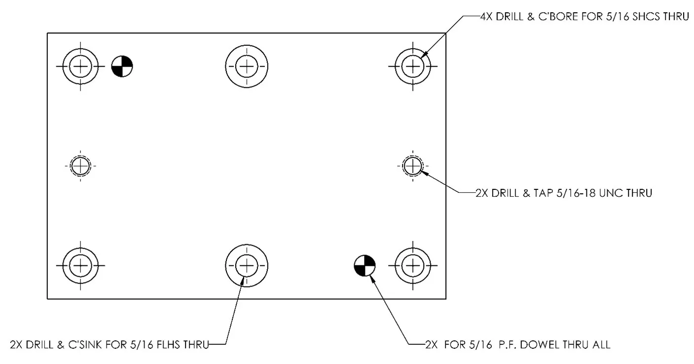
Here is what the same drawing looks like with the new callout file:
It’s important to understand these changes will not affect existing drawings with callouts. This will only affect new hole callouts. You will need to delete any existing callouts and re-create them to convert.
It’s not possible to have SOLIDWORKS look at multiple hole callout files at the same time. So if you need to switch back and forth depending on who the print is for, you’ll need to change out the location under tools, options, file locations, Hole Callout Format File. You can do this live without restarting SOLIDWORKS though to change how it calls out the next hole.
Contact us if you have any questions and we’ll be glad to give you a hand!
Learn More about Hole Callouts
SOLIDWORKS Hole Callout File Locations

About John MacArthur
John MacArthur is an Elite AE and the Engineering Manager - MidWest for GoEngineer. John’s hobbies and interests focus around designing and building cool things. He enjoys building and wheeling off-road machines, has an 80 lb. Pitbull named Thor, and likes to take broken things and return them to fully functional items.
Get our wide array of technical resources delivered right to your inbox.
Unsubscribe at any time.