SOLIDWORKS Pierce vs Coincident Relations & When to Use Each
Knowing how sketch relations affect your SOLIDWORKS model helps reduce errors and unwanted results. The two commonly misunderstood relations are Pierce and Coincident. It can be challenging to know when to use each relation because they seem to behave the same way in most situations. In this article, we discuss the difference between the two and why Pierce relations should always be used for features like sweeps and lofts.
Pierce Relations vs Coincident Relations
In a single 2D sketch, a Coincident relation tells the program to place a point connecting one entity to another, such as a line, arc, or ellipse. The point can move freely along the curve, meaning that the point is not fully defined. This flexibility can cause issues down the line if the model is changed.
The Pierce relation is only available when working with two intersecting planes, meaning between a sketch point and an external reference. An example would be a profile sketch and guide curves for a swept or loft feature. A Pierce relation will place a point at the exact location where the profile sketch meets the curve, while also fully defining the point.
How To Add Pierce Relations
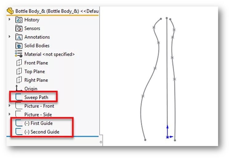
In the example below is a sweep path and two guide curves that will be used to sweep a profile to make a bottle.
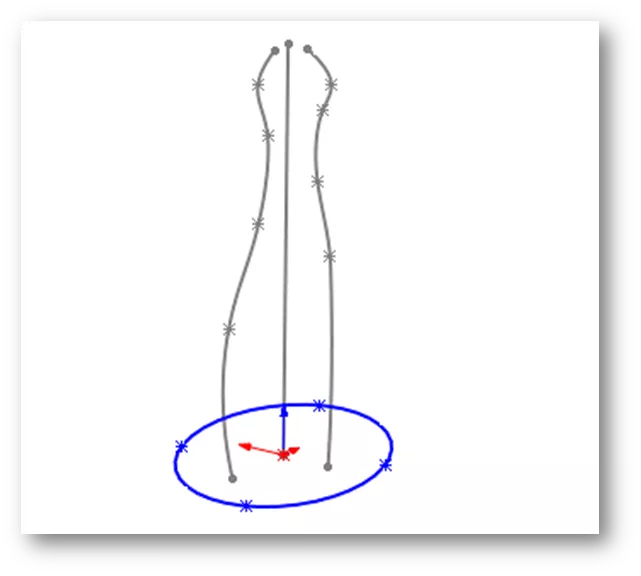
We’ll start a sketch on the top plane and draw an ellipse starting at the origin.
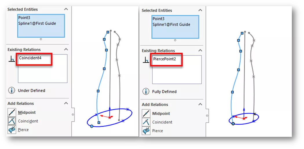
We'll hold CTRL and select the major axis point on the ellipse and anywhere along the first guide curve. The PropertyManager will appear where we can choose the Pierce relation. The two images below show what happens when Coincident is selected versus the Pierce relation. Note how the Coincident relation does not fully define the point at the curve.
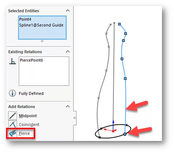
Next, we'll hold CTRL and select the minor axis point on the ellipse and anywhere along the second guide curve. Notice the ellipse is now fully defined.
Finally, we’ll exit the sketch, click Swept Boss/Base, and choose the ellipse for the profile sketch. For the sweep path, we’ll choose the straight line sketch, and for guide curves, we'll choose both first and second guide curve sketches.
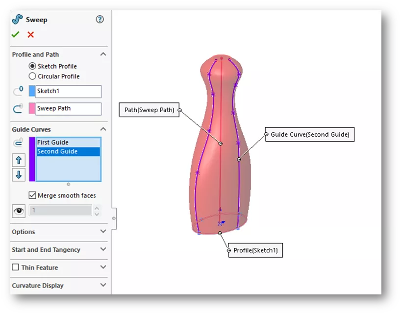
The Pierce relation allows the major and minor axis points to stay fully defined along the guide curves as the profile is being swept along the path.
I hope you found this SOLIDWORKS tutorial for Pierce vs Coincident relations and when to use each helpful. Sharpen your skills even more by enrolling in the official SOLIDWORKS Essentials training course.
Additionally, join the GoEngineer Community to participate in the conversation, create forum posts, and answer questions from other SOLIDWORKS users.

SOLIDWORKS CAD Cheat Sheet
SHORTCUTS ⋅ MOUSE GESTURES ⋅ HOT KEYS
Our SOLIDWORKS CAD Cheat Sheet, featuring over 90 tips and tricks, will help speed up your process.
More SOLIDWORKS Tutorials
Creating a Non-Circular Helix in SOLIDWORKS with Surfacing Commands
How to Make Threads in SOLIDWORKS: Basic and Custom
SOLIDWORKS Performance and How-To for Cosmetic Threads & Physical Threads
Using the Curve Through XYZ Points Tool in SOLIDWORKS
Introduction to SOLIDWORKS Mates: Standard, Advanced, & Mechanical

About Zach Brown
Zach Brown is a certified SOLIDWORKS Expert and a Technical Support Engineer. Prior to working at GoEngineer, he spent 15 years as a mechanical designer, CAD support tech, and instructor using SOLIDWORKS. His hobbies include playing guitar, riding motorcycles, and skiing.
Get our wide array of technical resources delivered right to your inbox.
Unsubscribe at any time.