Component Marks in SOLIDWORKS Electrical
In SOLIDWORKS Electrical, it is important to identify components with component marks. This mark is used to create relations to other representations of the device. When a symbol is added to a Schematic or Line Diagram, we can either define it as a component already defined in the project or create a new component with a new mark (identifier). In this article, we discuss the four ways a new symbol can get its mark.
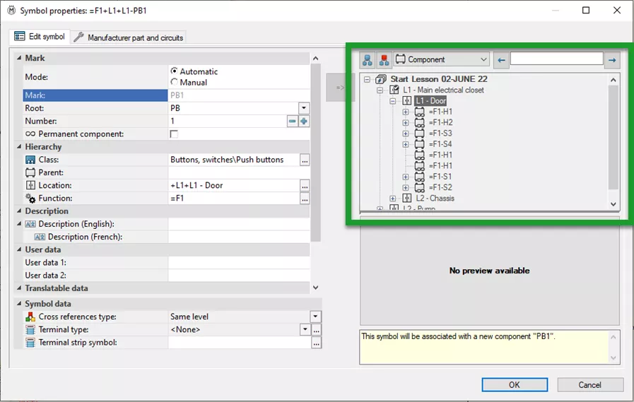
The first option will create an association between the two symbols in the project. When adding the symbol and creating the association to an existing component, we can use the drop-down filter in the upper-right portion of the Symbol Properties menu to quickly filter by component type and find the component we want to associate.
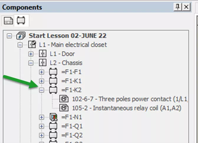
Once the component is selected, it will have the same mark as the existing component. In the Component Tree (in the example below), two symbols on different pages represent the same component.
The second option is to create a new component. This happens when placing a symbol on a page for the first time. You do not associate with an existing symbol or component. A new mark is created automatically.
How is this mark created, and where is it defined?
A mark is made up of at least two pieces: The root (M, PB, SS, CR) and a sequence number or other unique number. A mark can be automatically defined with a default from the symbol used for representation. As pictured below, when we create a new symbol or edit an existing one, we can define the component mark root.
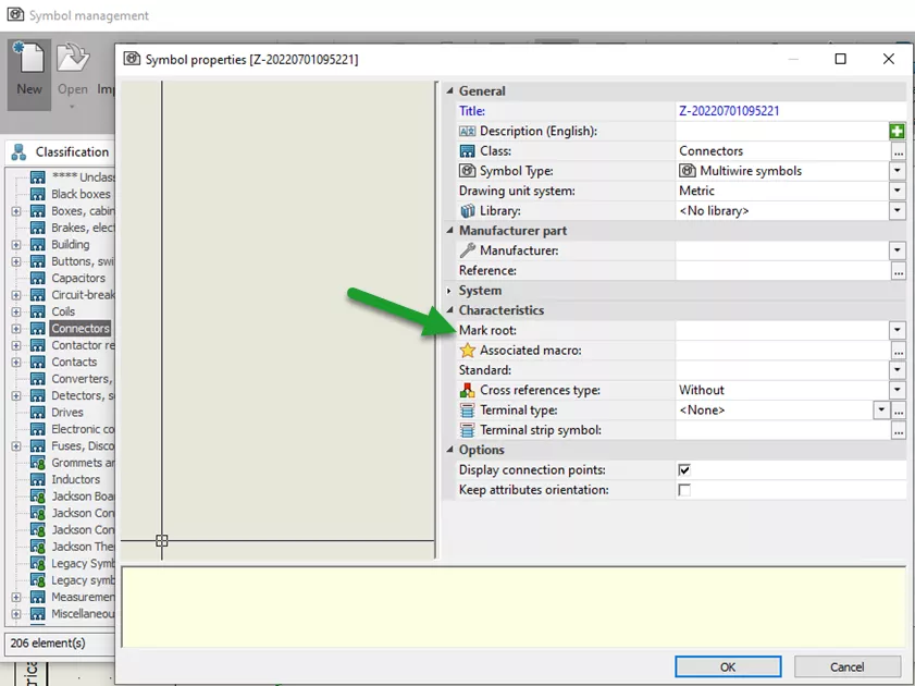
When a new symbol is added to a document, SOLIDWORKS will use the mark root taken from the symbol property and add a unique sequence number to create the mark. For example, when creating a new component with a root mark of “S”; if this is the first component that uses “S” as its root - it would become S1. The second symbol for a second component would become S2.
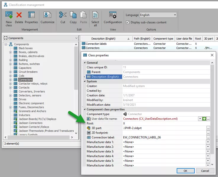
There is a third way a mark can be added to new components even if the symbol mark root is blank. If the symbol does not have a defined mark, when a new component is added, it will take the mark root defined by the classification of the symbol.
The fourth option for creating a mark is to define a formula. This is defined at the project level.
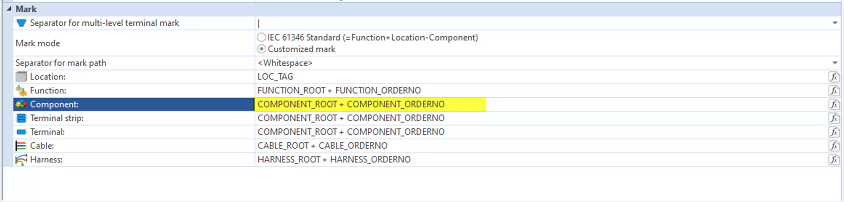
From the Electrical Project tab, go to Project Configuration and then the tab for Mark. In the mark section for components, the formula icon on the far right allows us to specify a different formula from the system defaults or define a custom formula.
I hope you found this article helpful. Learn more about SOLIDWORKS Electrical below.
Editor's Note: This article was originally published in July 2022 and has been updated for accuracy and comprehensiveness.
More SOLIDWORKS Electrical Tutorials
SOLIDWORKS Electrical 2024: Auto Balloons, Part Data, Ranges & More
How to Include External Data Files in a SOLIDWORKS Electrical Project
How to Create a SOLIDWORKS Rx in SOLIDWORKS, Electrical, and Composer
SOLIDWORKS Electrical Schematic Custom Line Types
About David Foster
David Foster is a Senior Electrical Specialist at GoEngineer.
Get our wide array of technical resources delivered right to your inbox.
Unsubscribe at any time.