Create Custom Symbols in SOLIDWORKS
Symbols are useful tools to simply convey valuable information in a SOLIDWORKS drawing. However, it may be useful to create a custom symbol for proprietary or other use.
There are two ways to create custom symbols in SOLIDWORKS: the easy way and the hard way.
The easy way utilizes SOLIDWORKS Sketch tools to create a block and may take 1-2 minutes.
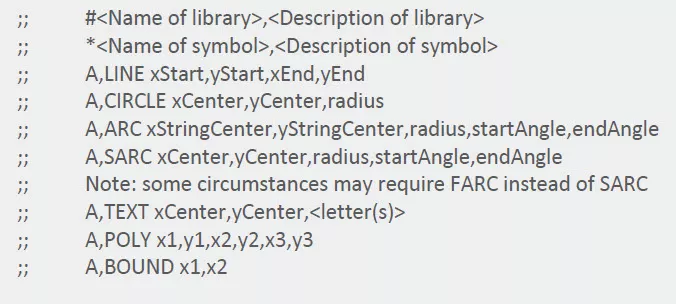
The hard way requires obtaining and understanding the language of the library file (gtol.sym) and determining the X-Y coordinate information (from 0.0 to 1.0) of the endpoints, arc radii, and the start and end angles of each entity you wish to be in your symbol. You will then need to enter that information without mistakes into the library file using Windows Notepad or a similar program. For instance, this is the format of the information you would enter into the gtol.sym file:
The only real advantage of creating a custom symbol in the gtol.sym file is that it will be consolidated with the other default symbols. The downside is it can be time-consuming and tedious to correctly create a custom symbol, and it is likely that the process will involve a lot of “guess and check.”
This is the example from the SOLIDWORKS Help website of a completed custom symbol:
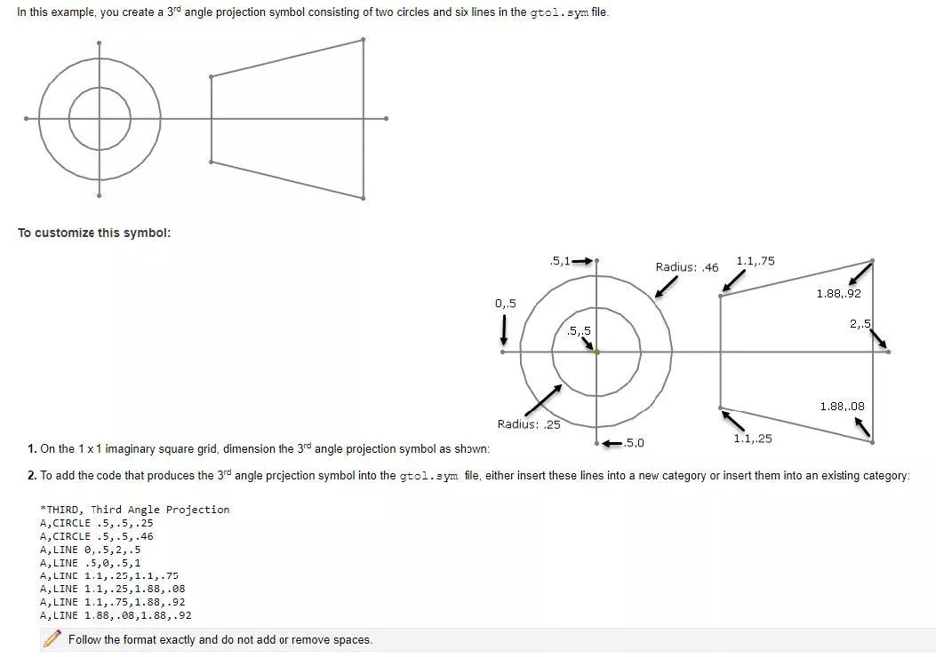
Figure 1: Example format of creating a 3rd angle projection symbol
Sound like fun? If you’re someone who would prefer to make this using coordinates and put it into the library file, follow these instructions from the SOLIDWORKS Help website.
In this post, I will demonstrate the easy way, which is simply to create a Block using Sketch tools. In this example, I will create a field weld symbol using the following steps:
- Open a new SOLIDWORKS Drawing file. Open a small template such as an A size for simplicity.
- Use the Sketch tools and sketch a hexagon using the Polygon tool. Sketch an additional line to connect two opposite endpoints (see Figure 2).
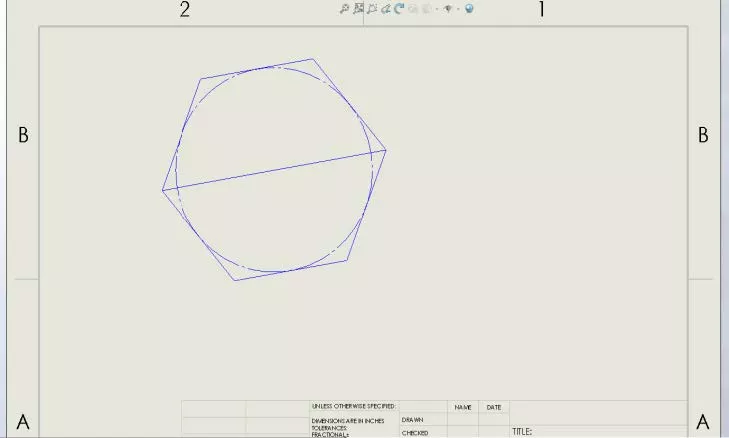
Figure 2: A sketched hexagon polygon - Add a Horizontal relation to the middle line and set the length to 0.75”. Delete the construction circle.

Figure 3: Complete sketch - Add two notes to the symbol (one to the top half, one to the bottom half). Change the font to 10-point, center-aligned. In the top half, type FW, and in the bottom type 1.

Figure 4: Completed block - Create a new block using Annotation > Blocks > Make Block or Tools, Block, Make. Drag-select all entities.
- Before clicking the green checkmark, expand the Insertion Point section in the PropertyManager (left toolbar).
- Set the insertion point on the left endpoint of the hexagon and place the origin in the center. Click the green checkmark.
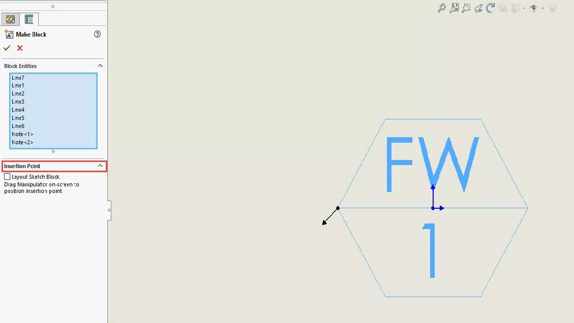
Figure 5: Moving the manipulators of the block - Right-click the block and select Edit Block.
- Select the FW note. In the PropertyManager, add the attribute name FieldWeld. Check Read only.
- Select the 1 note. Add the attribute name Number. Clear Read only.
- Exit the block, saving changes.
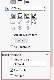
Figure 6: Modified block attributes
You’ve now successfully created your custom symbol!
Block Tricks
To insert additional instances of the symbol:
- Expand the Blocks folder in the FeatureManager. Simply drag your block into the drawing. You can also use the CommandManager Annotation > Blocks > Insert Block.
To instance a symbol:
- Quick: Left-click the block. Doubleclick the 1. The value can now be modified to 2, 3, 4, etc.
- In-depth: Left-click the block. In the Text/Dimension Display section of the PropertyManager, click the button Attributes…. The values of multiple attributes can now be modified.
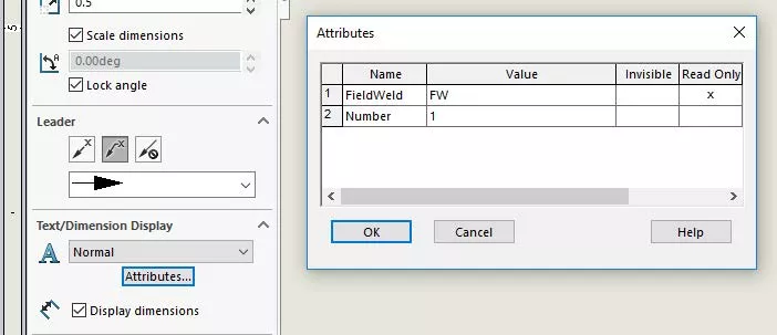
Figure 7: Attributes property box
To add a leader to the symbol:
- Left-click the block. In the Leader section of the PropertyManager, select Straight Leader or Bent Leader. A leader will be connected to the insertion point.
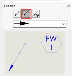
Figure 8: attached leader
To share the symbol with others:
- Right-click the block, select Save Block. Save the .sldblk file with a distinct name to a location where others can access (network drive, PDM vault, etc.).
- Others will need to add the block's location to their Tools > Options > File Locations. Change the drop-down option to Blocks. Click Add… and select the folder in which the block is located.
- After successfully adding the file location, click Insert Block. The block will show in the PropertyManager window.
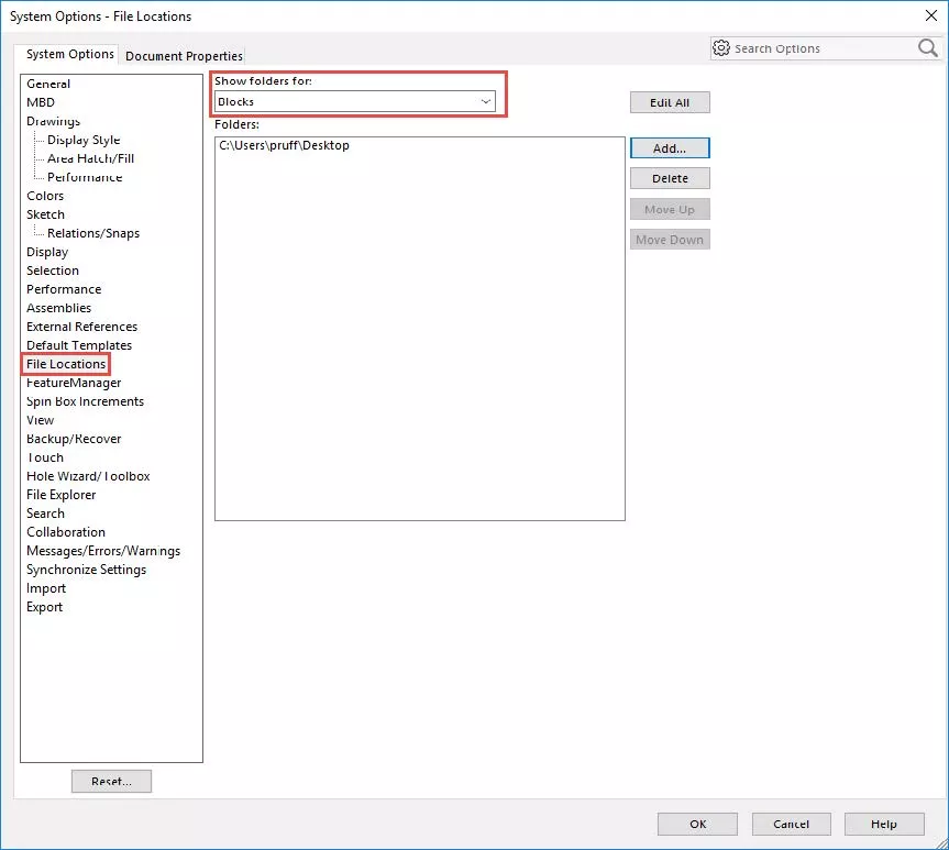
Figure 9: Adding the block’s saved location
More SOLIDWORKS Tutorials
SOLIDWORKS Mold Tools - Draft Analysis and Scale
SOLIDWORKS Copy and Paste Features: Same or Different Parts
SOLIDWORKS Routing 101: Pipe Design
How to Create a Lip/Groove Feature in SOLIDWORKS

About Preston Ruff
Preston Ruff is a Technical Support Engineer and Certified SOLIDWORKS Instructor based out of our Headquarters in Salt Lake City, Utah. He earned a Bachelor’s degree in Manufacturing Engineering Technology from Brigham Young University and is a Certified SOLIDWORKS Expert. For many years, Preston has been passionate about CAD design, 3D printing, additive manufacturing, and being involved with STEM education. He joined the GoEngineer family in 2017.
Get our wide array of technical resources delivered right to your inbox.
Unsubscribe at any time.