SOLIDWORKS Fit Spline Explained
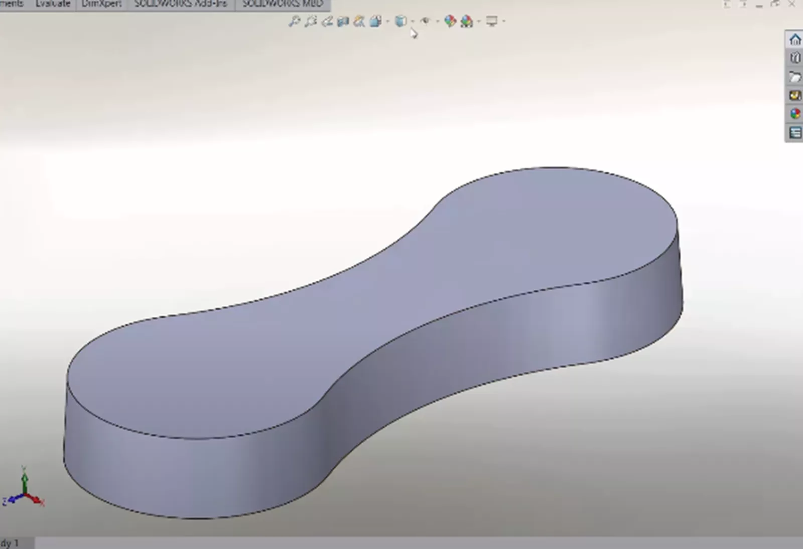
In SOLIDWORKS , have you ever noticed hard edges at conjoining surfaces, surfaces intended to be one continuous bend? Digitally, these are not a hindrance to our work, but these hard edges can appear on manufactured products, especially products made on a CNC machine or through plastic injection molding.
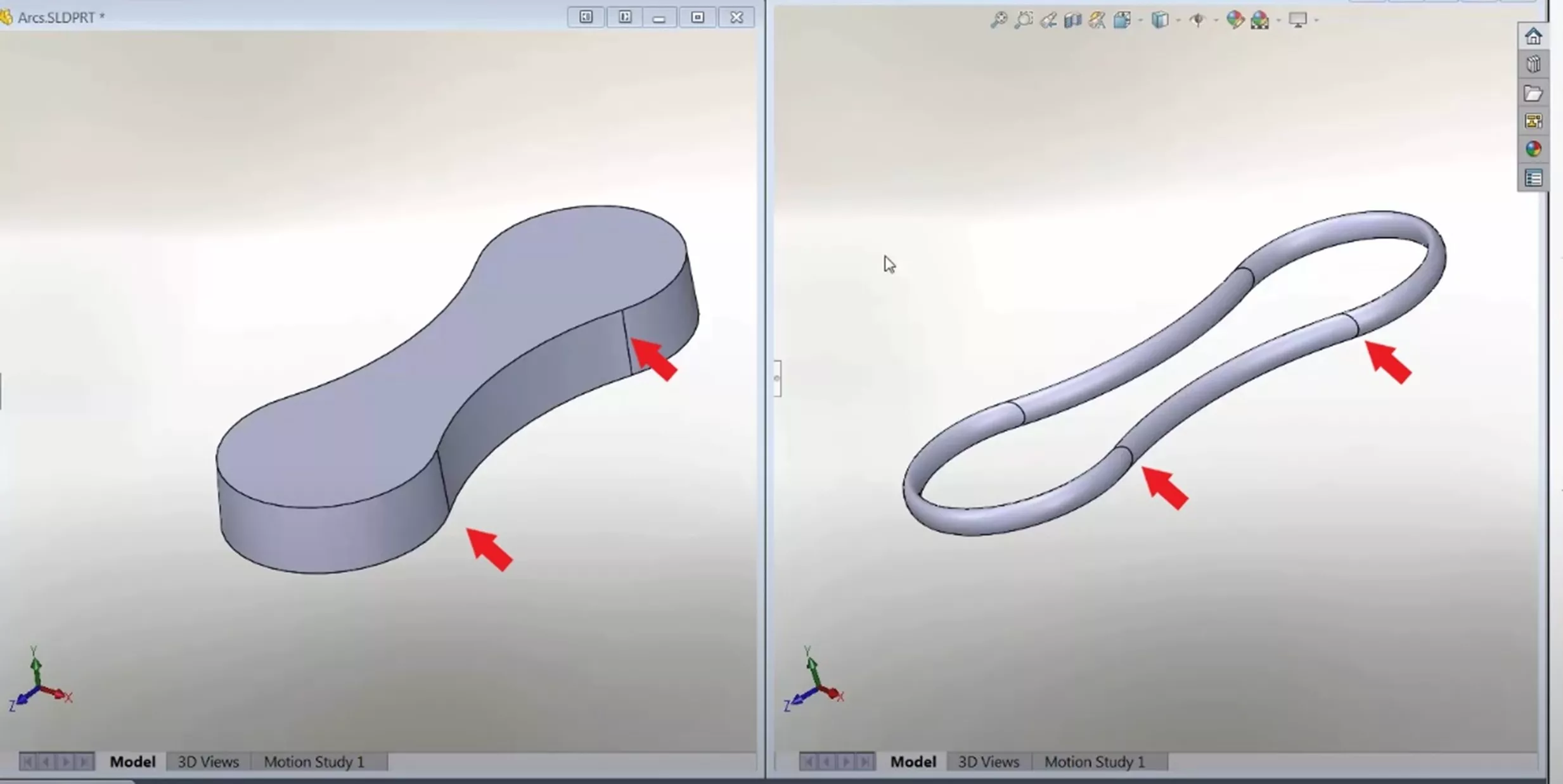
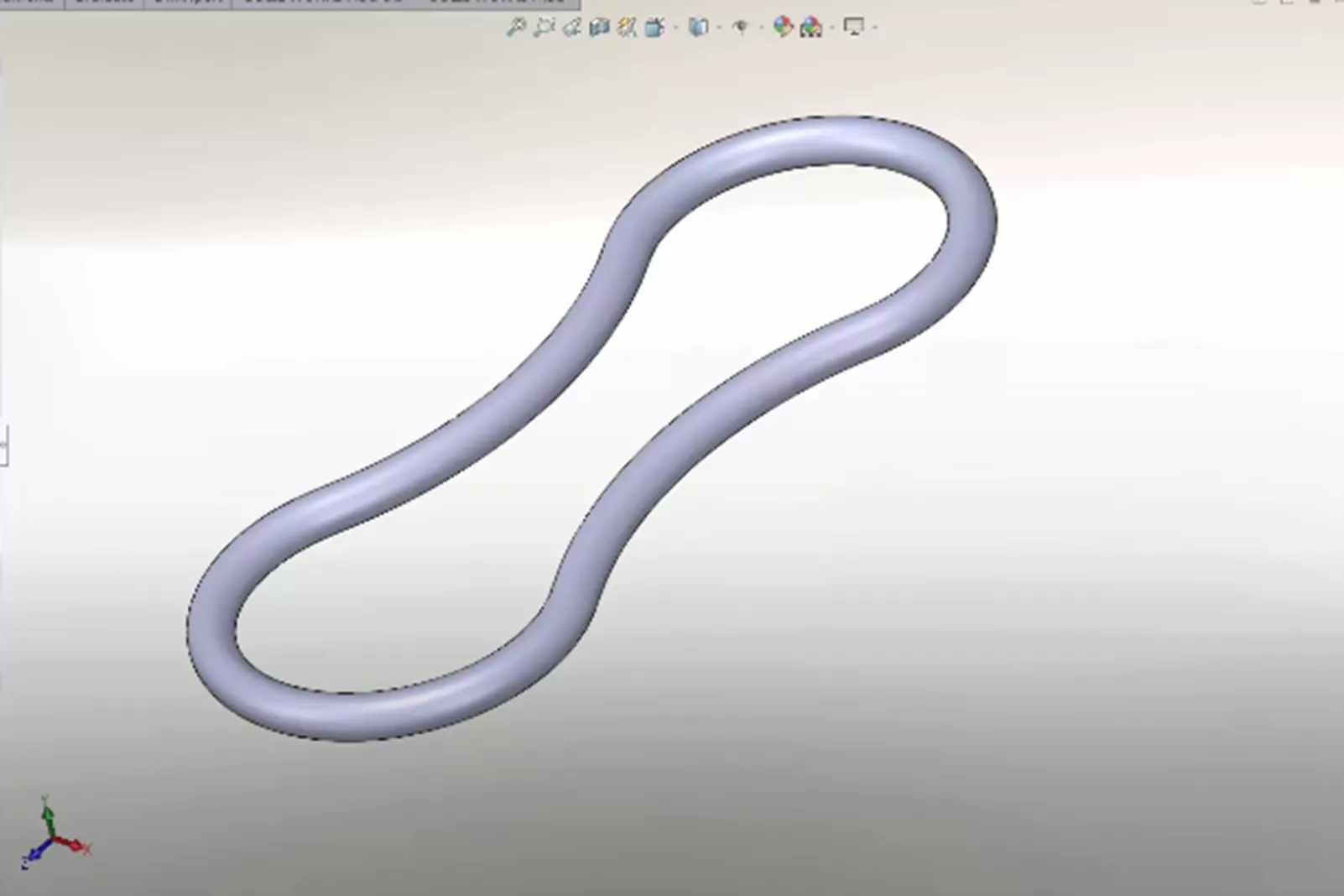
Fit Spline is a tool in SOLIDWORKS that can help clean up these edges to produce a single, smooth surface. Fit Spline takes two different lines, curves, or splines and smooths the junction to a continuous unbroken line.
How to use Fit Spline
To access Fit Spline, go to Tools > Spline Tools > Fit Spline.
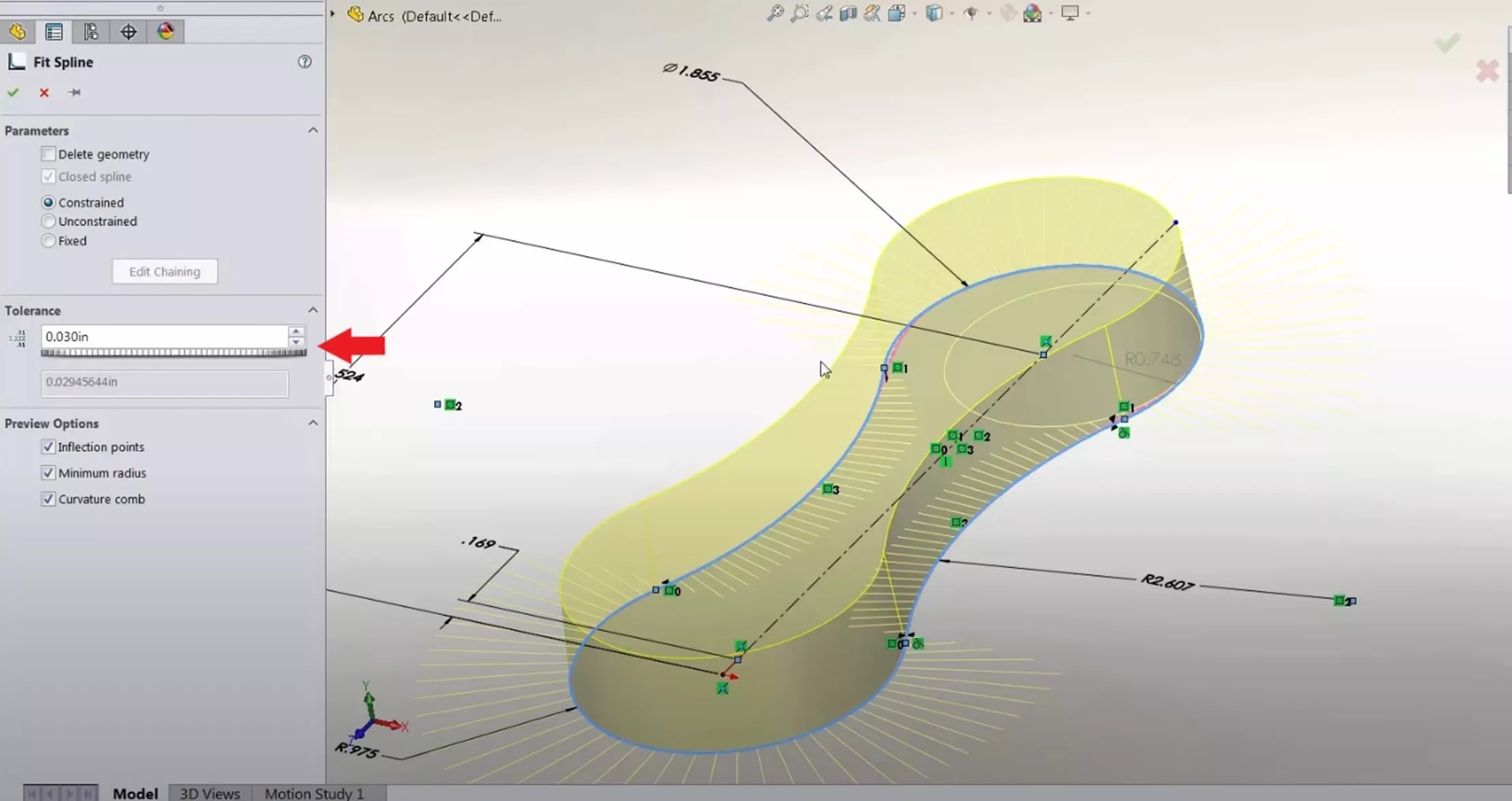
Once a basic shape is created using lines, arcs, and/or splines, Fit Spline can be used to edit the shape and remove the hard edges.
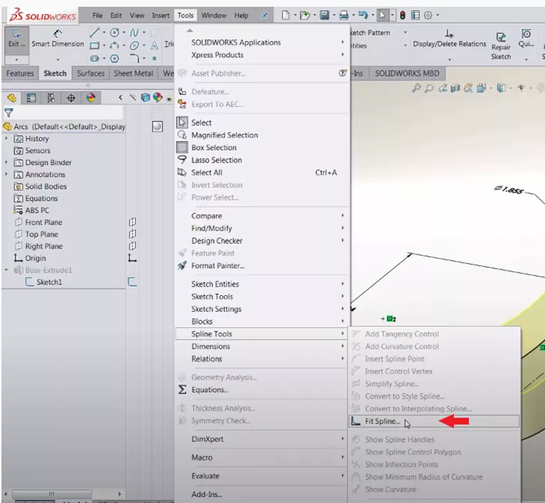
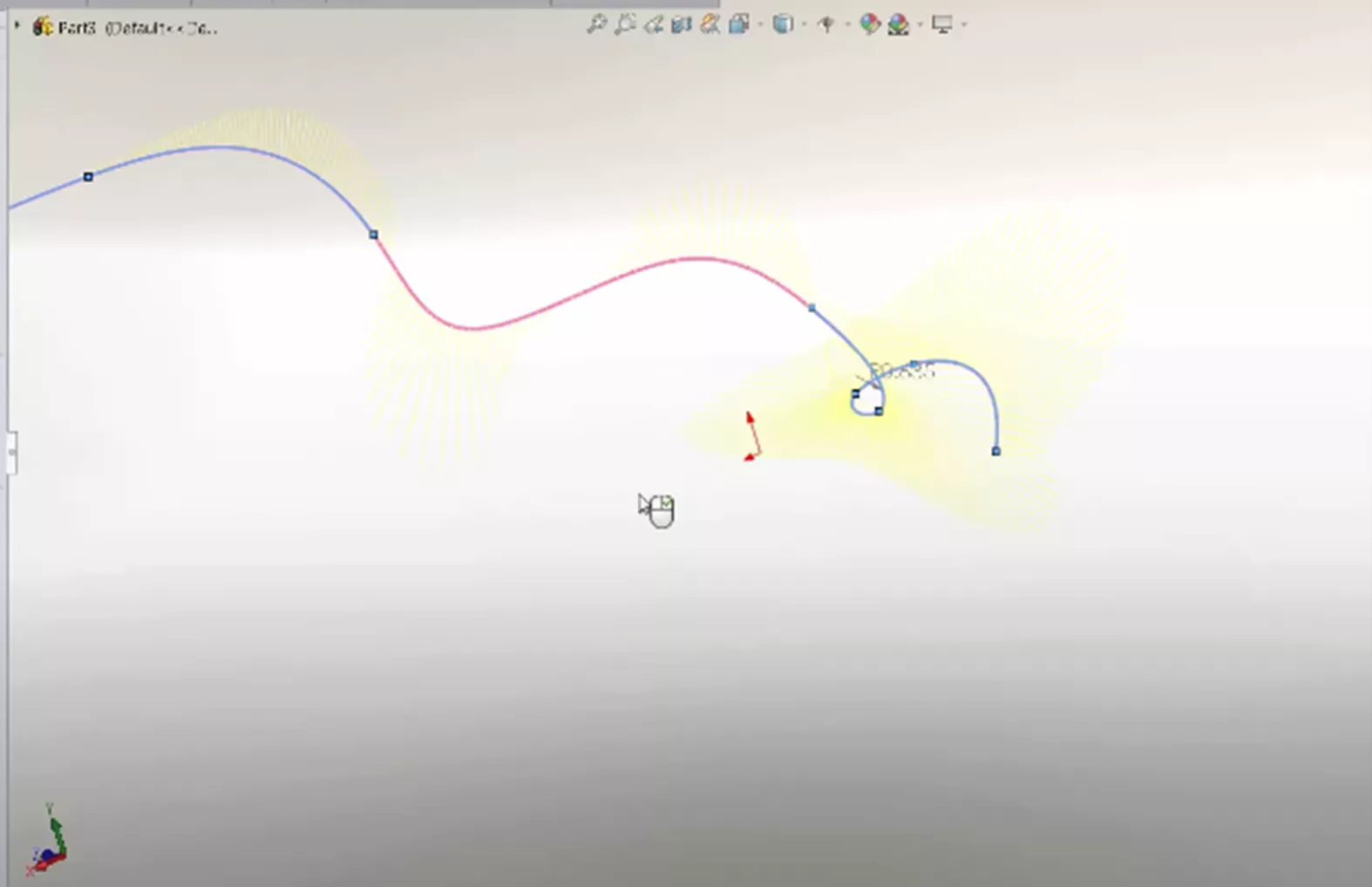
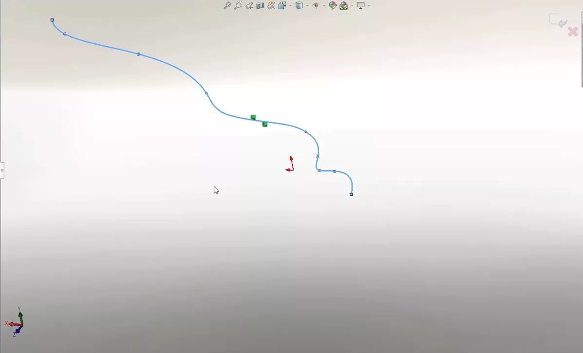
With the Fit Spline command open, select the geometry in which to alter. In this example, the geometry we want to alter is the sketch the body is extruded from. When the geometry is selected, Fit Spline shows a preview; we can then adjust the Tolerance. If we increase the tolerance, Fit Spline will smooth out the hard edge as cleanly as the tolerance allows.
Different Uses of Fit Spline
Above we discussed how to use Fit Spline, and as an example, we smoothed out the hard edges of a closed loop sketch. Fit Spline can also be used on Open Loops.
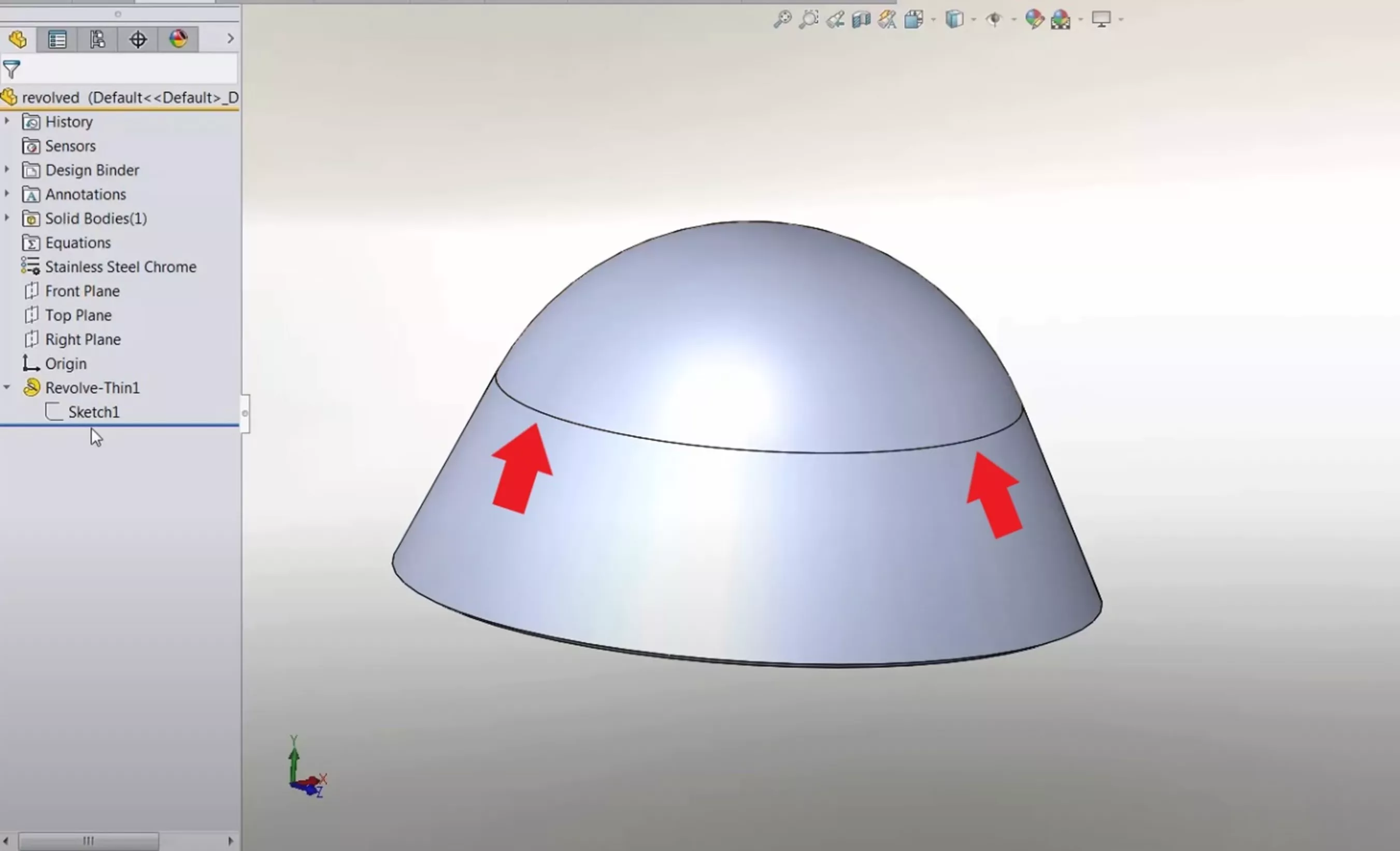
For example, Fit Spline can be used to clean and smooth out the hard edges on a revolve. In the revolved part below, we can see there is a hard edge on the model that could show up in manufactured parts.
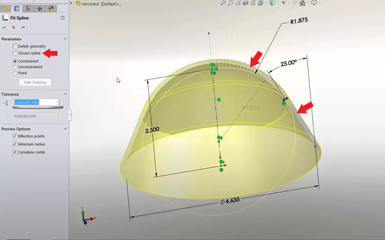
Edit the sketch of the revolve, select the geometry to alter, and then open the Fit Spline tool.
On an Open Loop sketch, ensure that the Closed Spline option in the Fit Spline tool is not selected; otherwise, it will automatically try to close the loop.
Fit Spline between 3D Geometries
Another use for Fit Spline is to automatically connect two different 3D geometries with a spline.
To do so, select two geometries and then open the Fit Spline command. Similarly to the other uses, we can adjust the Tolerance of the Fit Spline and edit the additional options.
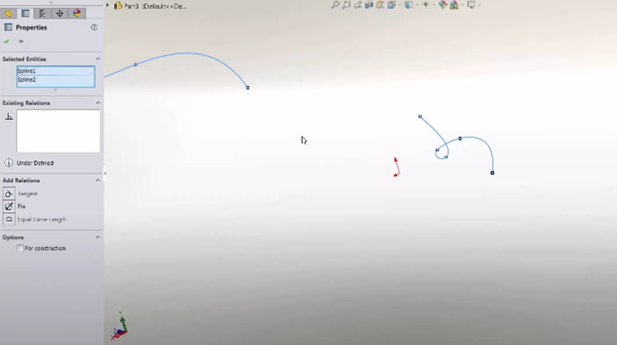
This will automatically generate a spline to fit between the two geometries.
SOLIDWORKS Fit Spline Demo
For more information on the Fit Spline tool, watch the video below for a demo on using this tool.
Learn More About SOLIDWORKS Splines
Ultimate Guide to SOLIDWORKS Splines
SOLIDWORKS Tutorial: Edit, Create, & Convert Style Splines
Using the Curve Through XYZ Points Tool in SOLIDWORKS
Introduction to Continuity and Curvature in SOLIDWORKS (Part 1)
About Kaden Sumsion
Kaden is a SOLIDWORKS Technical Support Engineer at GoEngineer.
Get our wide array of technical resources delivered right to your inbox.
Unsubscribe at any time.