What is Topology Optimization - SOLIDWORKS Simulation
Topology Optimization is a technique in SOLIDWORKS Simulation that removes material from a user-defined shape or design space to maximize the the performance of the shape. Performance, in this instance, would be maximizing stiffness to weight ratio, minimizing displacement, or a combination of the two for a given set of loading conditions.
How to Use Topology Optimization
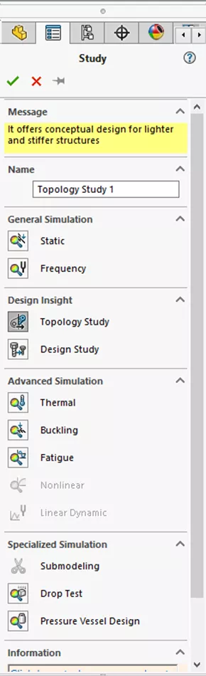
To use the Topology Optimization technique, simply create a new Simulation study; this will allow you to pick the Topology Study option within the available study types. (Note: Topology Optimization is exclusively available in SOLIDWORKS Simulation Professional and Premium)
Once the new study is created, set it up as normal by going through the tree and getting it ready to run. Once finished with the essentials, you’ll need to define the optimization problem. To do this, go to Goals and Constraints, right mouse button, then select Best Stiffness to Weight Ratio.
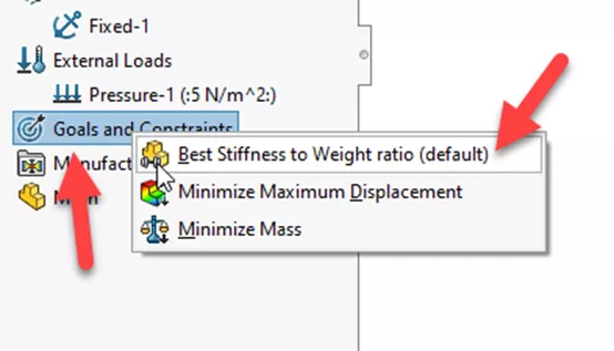
When setting up, the goal is to maximize the stiffness of this component.
Manufacturing Controls allow you to impose restrictions on where and how the material is removed. With SOLIDWORKS Topology, there is a pre-defined 'keep out' zone around areas of load and constraint application. You can edit this information to better work for you. Be sure to set up any other needed items from the list (e.g.,. demold or symmetry control).
Once the pre-requisites have been set up, we can mesh the study and run.
The solver uses an iterative convergence process during the solution phase for the goals in the constraint to achieve an optimum design, so the values input with Goals and Constraints as well as Manufacturing Controls will affect their final shape.
Results are in!
Once the solution is converged, you have a final opt by state.
With this information, you can use the post-processing options within SOLIDWORKS to determine how much material can be removed and where from.
You can also use the .STL file for 3D printing or to generate a parametric shape.
It is customary to test the final shape of the model once it has been finalized, using the same boundary conditions from the original study. You can also run a design study on the finished product as well.
SOLIDWORKS Simulation Topology Optimization Demo
Check out the video below for a demo of and use case of these best practices.
More SOLIDWORKS Simulation Tutorials
SOLIDWORKS Simulation Nonlinear Material Model Type Setup
SOLIDWORKS Simulation Variable Amplitude Time History Fatigue Tool Tutorial
SOLIDWORKS Simulation Plot Legend Options
SOLIDWORKS Simulation Analysis Productivity Tips

About Krystal Petersen
Krystal Petersen is a SOLIDWORKS Technical Support Engineer based out of Auburn Hills, Michigan. Krystal studied Product Engineering at Oakland Community College and has earned her CSWA and CSWP Certifications. She joined the VAR channel in 2015 with DASI (now GoEngineer). Krystal is a huge fan of Star Wars and likes to spend her off time fishing and camping.
Get our wide array of technical resources delivered right to your inbox.
Unsubscribe at any time.