How to Make Threads in SOLIDWORKS: Basic and Custom
Let's take a look at how to make threads in SOLIDWORKS. The good news is that ever since the release of SOLIDWORKS 2016, the process couldn’t be easier. There are basic threads and custom threads. I’ll show you how to make both. Let’s get started.
How to make Basic threads in SOLIDWORKS
To make a thread in SOLIDWORKS we can simply to go Insert > Features > Thread. We then choose an edge of our model and go through and populate our thread specifications. Once we’re done doing that, we can hit the green checkmark and there are our threads. It really doesn’t get any easier than that.
But a lot of users want to know how to create their own threads in SOLIDWORKS by sketching their own profile and doing a swept cut.
How to make Custom threads in SOLIDWORKS
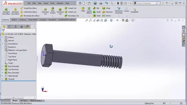
To do this we’re going to start off with the helix we created in my previous blog as we were modeling this hex cap screw. Go to the top plane and begin a sketch. Now, the reason we’re using the top plane is that when we created the helix, the helix ended at zero degrees, so that’s exactly where our top plane is.
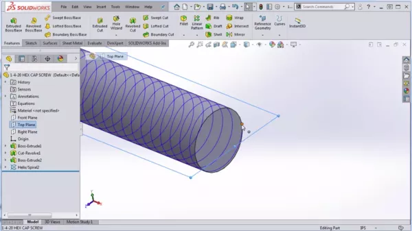
We’re starting a new sketch on the top plane and now we’re ready to sketch the actual thread profile. This is where the real magic happens because there are a lot of different techniques to do this, where should the plane be located, and ideally you’re going to stick the specifications in the Machinery’s Handbook. But if you don’t have those specifications or if you’re creating a custom thread, then you might have a little bit more play as for how you create your thread.
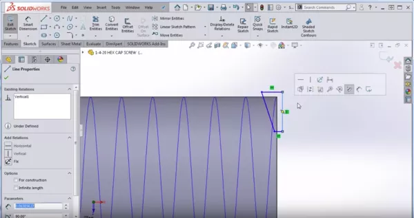
Personally, I like to create half of the thread first. Then I take the vertical line (as shown below) and make it for construction. Next, I’ll take a window selection of the entire sketch and select the Mirror Entities command which gives me the same thread profile on both sides of the center line.
Next, I will take a point and put it anywhere on the center line. Then I'll put a dimension from that point to the very top line. The reason I have that dimension there is because I want there to be a little bit of overlap between where the thread is cutting and the very outer most part of the shaft by just a few thou (maybe 0.003 inches).
Now, I’m going to click on that point that I sketched and I’m going to hold Control and select the helix. Next, I’m going to assign what’s called a pierce relation. That’s going to hook that sketch to the helix exactly at that point.
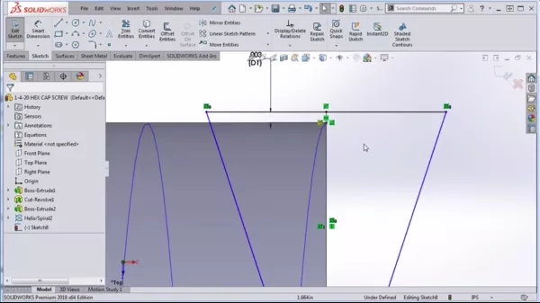
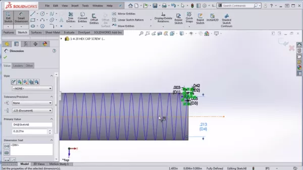
Now I’m ready to put in my final dimensions and say I want the distance from peak to peak to be .042 (the pitch is .050 so that should get me more or less in the ballpark). I‘m going to make the flat at the bottom five thou just to get myself close. Reminder: I know these aren’t exactly the right numbers from the Machinery’s Handbook but I’m just trying to give you something close to work off of.
Finally, I’m going to fully define my cutting tool by defining the pitch dimenions. If I look at my spec sheet, it is .2127. Now that should give me something that looks pretty good for this cut thread.
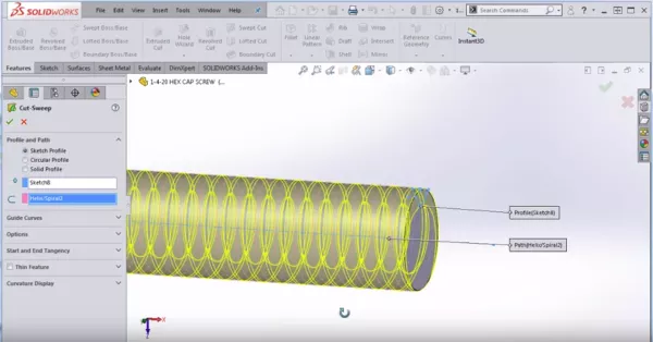
Now, I’m going to exit that sketch and I’m going to go to Features > Swept Cut and I’m going to choose to sweep that sketch that I created along the helix. I’m seeing a preview which means I should be going in the right direction. I'll click the green check mark and there we go! We were able to do a cut sweep of our thread!
To create the lead in for this part up at the top, I like to create a simple cut revolve. You don’t have to do this with a chamfer, in fact, you might struggle to do it with a chamfer because there’s not really a clean edge there to chamfer off but you can do it quickly and easily by creating a simple triangle. To see another example of how to make threads in SOLIDWORKS, check out our tutorial on the thread feature.
Professional SOLIDWORKS Training from GoEngineer
Learn more about the essential modeling techniques in SOLIDWORKS in our SOLIDWORKS Essentials training courses. These courses are offered in person, live over the web, or on-demand.
![]()
About GoEngineer
GoEngineer delivers software, technology, and expertise that enable companies to unlock design innovation and deliver better products faster. With more than 40 years of experience and tens of thousands of customers in high tech, medical, machine design, energy and other industries, GoEngineer provides best-in-class design solutions from SOLIDWORKS CAD, Stratasys 3D printing, Creaform & Artec 3D scanning, CAMWorks, PLM, and more
Get our wide array of technical resources delivered right to your inbox.
Unsubscribe at any time.