SOLIDWORKS Electrical 2D: Changing the Automatic Root Value for Symbols
This article explains how to change the automatic root value for symbols inserted into the SOLIDWORKS Electrical documents (Single-line and Multi-line schematics). A symbol is just one representation of a Component. When making changes to a symbol already placed on a page in a project, remember that the overall component must be looked at, not just the symbol.
The first time a symbol of a device is placed into a project, the symbol becomes the first representation of your component.
Whenever a symbol is placed in SOLIDWORKS Electrical, it will automatically assign it a component ID. This designator, by default, is made up of a root mark followed by an order number.
The default root marks are determined by the class of the symbol. For example, motor symbols are in the motor class and the property of this class then gives the Component a default label of “M”. When placing a motor on a page, the identification of the component would be M1. The second motor then becomes M2.
Have you ever wished that certain symbols would automatically default to a different value instead of what they are currently set to? It can be frustrating to have to manually change the root mark value every time you insert the symbol into a drawing. This repetitive task can become tedious. Let’s walk through how to set up the default root marks for the different classes. We are going to change the circuit breaker default from Q to CB.
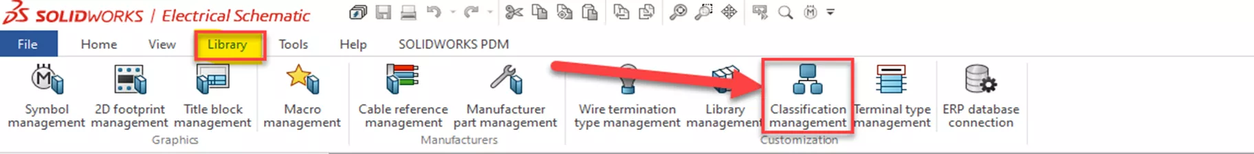
In SOLIDWORKS Electrical, click the Library tab in the upper ribbon. Activate the Symbols/Parts Classification Manager by clicking the Classification management icon.
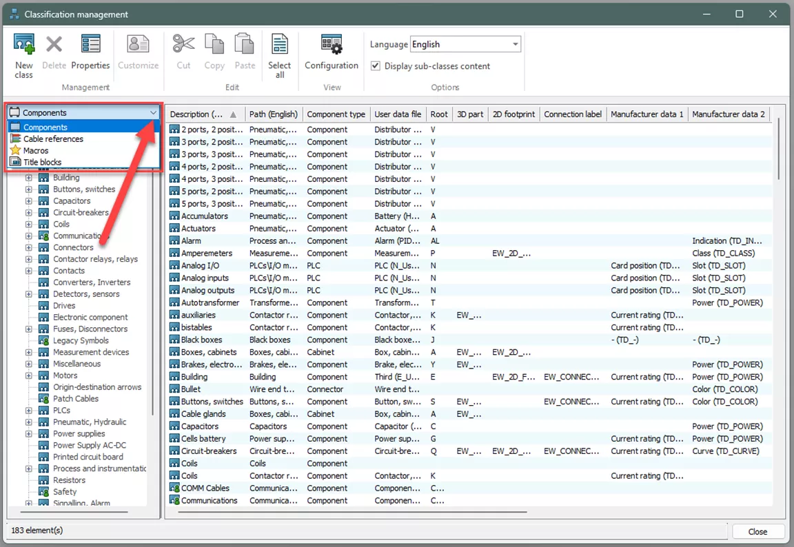
Select the type of items you want to view. Select Components.
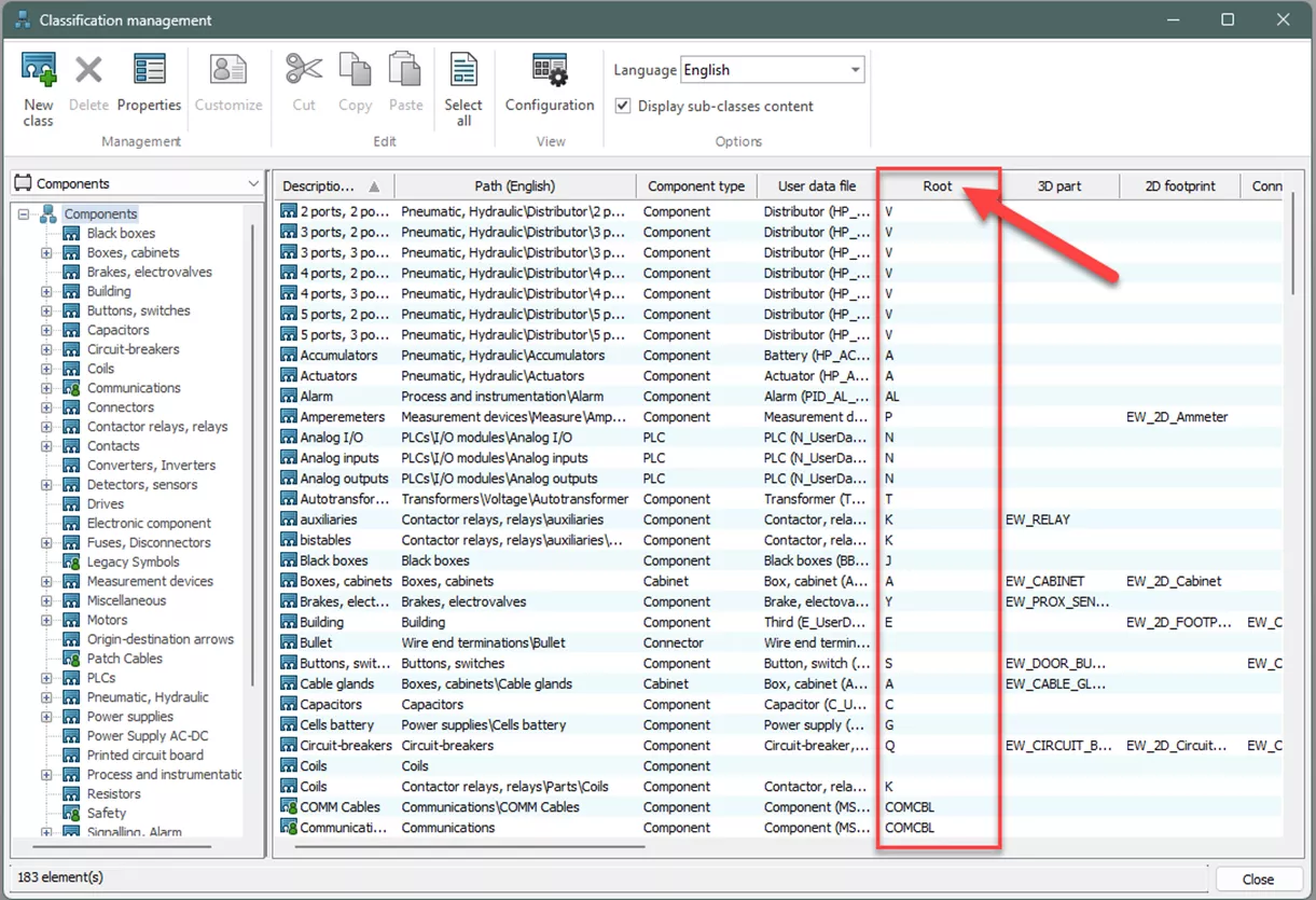
A root (i.e., A, Y, etc.) is associated with each classification and sub-classification. The root can be changed by double-clicking in the corresponding field of classification or sub-classification.
Some Classifications have sub-classes, which can be examined by selecting the expand or plus sign on the left-hand side of the dialog box (this can be easily seen when examining buttons, switches, etc.).
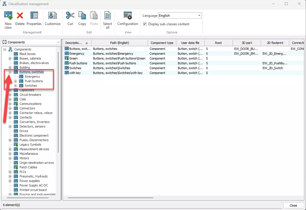
When changing the root for the classification, the sub-classification will take on that same change.
Notes
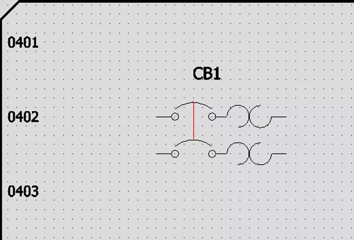
If the Root field is changed, the corresponding symbol will have that Root Mark by default when dropped on a schematic or line diagram. For example, if the root for the circuit breakers is changed from Q to CB, then the symbol will be marked as CB1 if that is the first instance of a circuit breaker inserted into the schematic (shown below).
Base classification and sub-classifications use the same User Data File. This is why, when changing the root for any portion of a specific classification, the entire class, including the sub-classes, adopt the same change to the root.
This does not affect components already placed into the project; only new components added to the project after the change is made.
A component’s root mark can also be changed manually by right-clicking on the symbol and clicking Component properties. Here, a root and number can be changed.
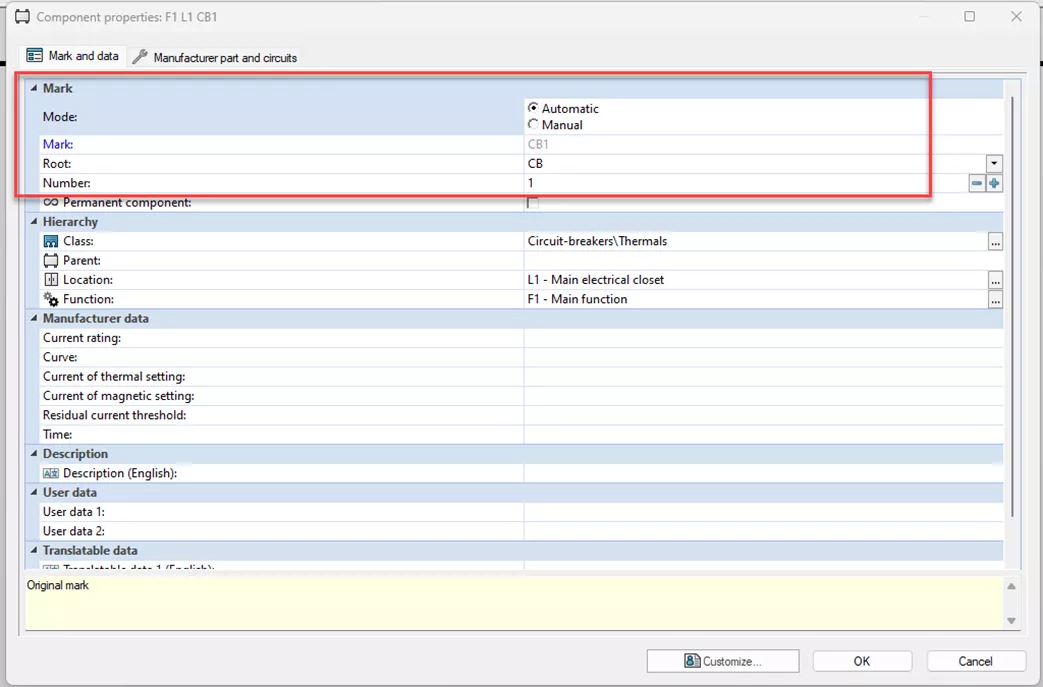
You can keep the Mark as Automatic. Changing the Root from CB to DISC and clicking off the field; notice the Component Mark change. Be careful NOT to add a number in the ROOT field. Adding a number in the Root field (CB1) would cause the software to make a component ID of Root being CB1, to the number being 1, ending with a result of CB11.
So again, a number will be added when the software uses the automatic formula. It will automatically add the number to the ROOT to produce the correct Component ID.
I hope you found this article helpful. Learn more about SOLIDWORKS Electrical below or visit our video library.
Editor's Note: This article was originally published in January 2014 and has been updated for accuracy and comprehensiveness.
More SOLIDWORKS Electrical Tutorials
Component Marks in SOLIDWORKS Electrical
SOLIDWORKS Electrical 2024: Auto Balloons, Part Data, Ranges & More
How to Include External Data Files in a SOLIDWORKS Electrical Project
How to Create a SOLIDWORKS Rx in SOLIDWORKS, Electrical, and Composer

About Cheri Guntzviller
Cheri Guntzviller is a Senior Electrical Specialist with over 35 years’ experience. She earned her Bachelor of Science in Electrical Engineering degree from Lawrence Technological University and joined the VAR channel in 2013 with DASI (now GoEngineer). She is a problem solver and is passionate about teaching and helping others solve problems. Based out of Michigan Cheri enjoys gardening, fishing, construction, and spending time with her family and pets. Cheri is a SOLIDWORKS Certified Electrical Specialist, Trainer, and Professional Presenter.
Get our wide array of technical resources delivered right to your inbox.
Unsubscribe at any time.