What's New SOLIDWORKS 2022: Simulation, Flow, & Plastics
In this article, get a sneak peek at what’s new for SOLIDWORKS Simulation, Flow Simulation, and Plastics.
SOLIDWORKS Simulation 2022
SOLIDWORKS Simulation 2022 offers improved solve time, a brand new connector, and enhanced contact performance.
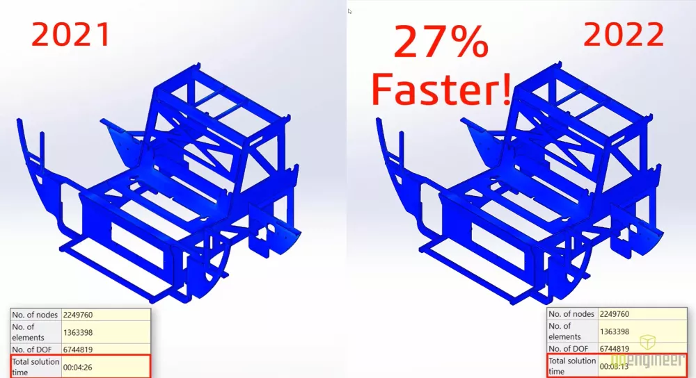
The NEMO frame assembly below has several bonded contacts. In SOLIDWORKS Simulation 2022, users can now expect solve time to be 25% faster than previous releases.
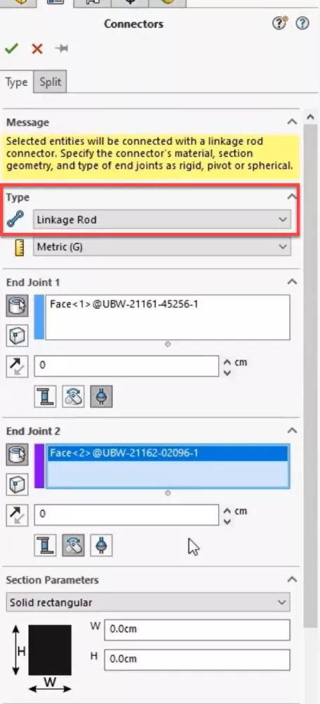
SOLIDWORKS Simulation 2022 also has a new Linkage Rod connector. Users can specify cylindrical faces, circular edges, or vertices, plus indicate the end condition by specifying rigid, spherical, or pivot.
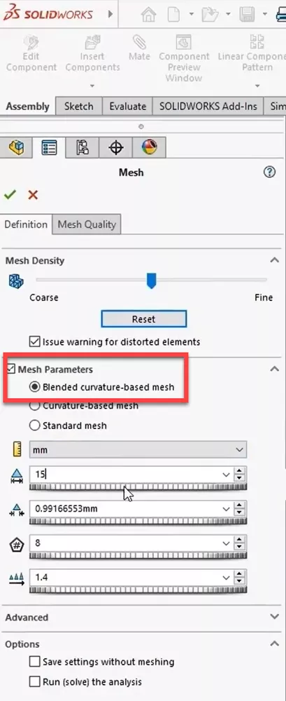
Users will also notice that the default mesh type is now the powerful Blended curvature-based mesh which now allows mesh controls. Even with a refined mesh, we see improved solve times, especially with the FFE solver.
These simulation improvements will allow you to make better and faster design decisions.
![]() See these new features in further detail and more of what's new in SOLIDWORKS Simulation 2022 in this video.
See these new features in further detail and more of what's new in SOLIDWORKS Simulation 2022 in this video.
SOLIDWORKS Flow Simulation 2022
SOLIDWORKS Flow Simulation 2022 offers enhanced features for Transient studies.
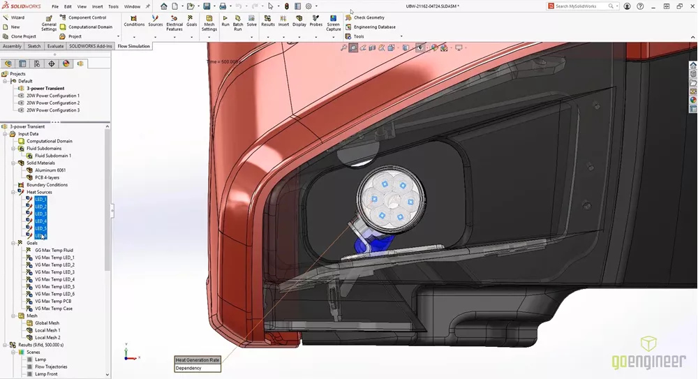
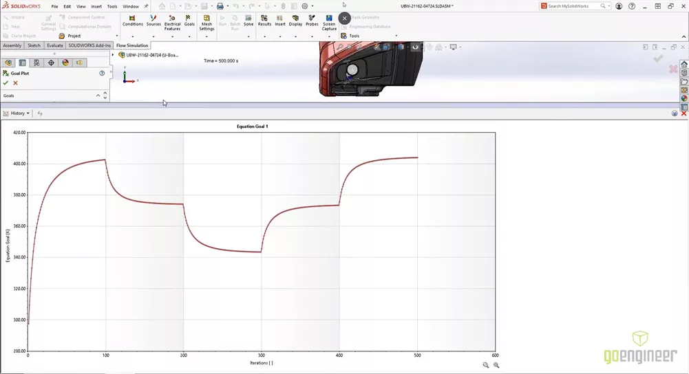
In the example below, the NEMO has a new lamp with three different brightness settings. Here, we can run the Transient Analysis while switching the power settings of the bulb.
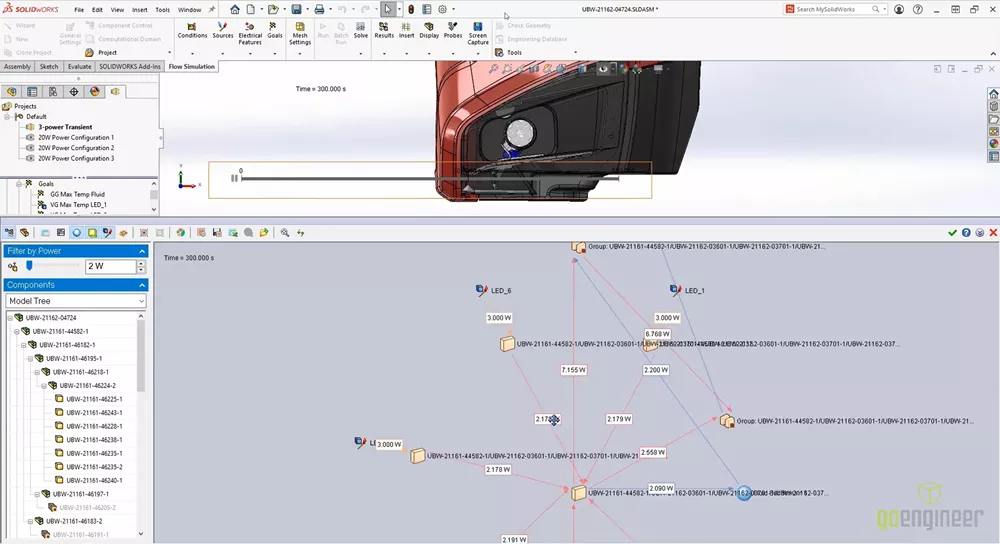
Users can now view a Flux Plot in the transient explorer to see how power is moving in and out of the system.
Users can also create a new equation goal based on other defined goals.
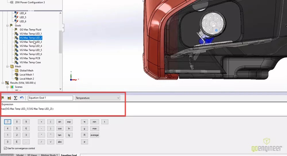
Here we can calculate the max temperature of all the LEDs in the transient analysis.
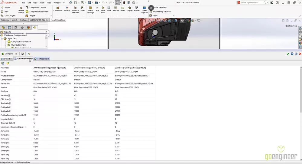
Also new in Flow Simulation 2022 are tools available for interrogating and comparing studies. Users can now merge studies to view the maximums across results, we can see a difference plot, and a results summary that tabulates the comparison.
![]() See these new features in further detail and more of what's new in SOLIDWORKS Flow Simulation 2022 in this video.
See these new features in further detail and more of what's new in SOLIDWORKS Flow Simulation 2022 in this video.
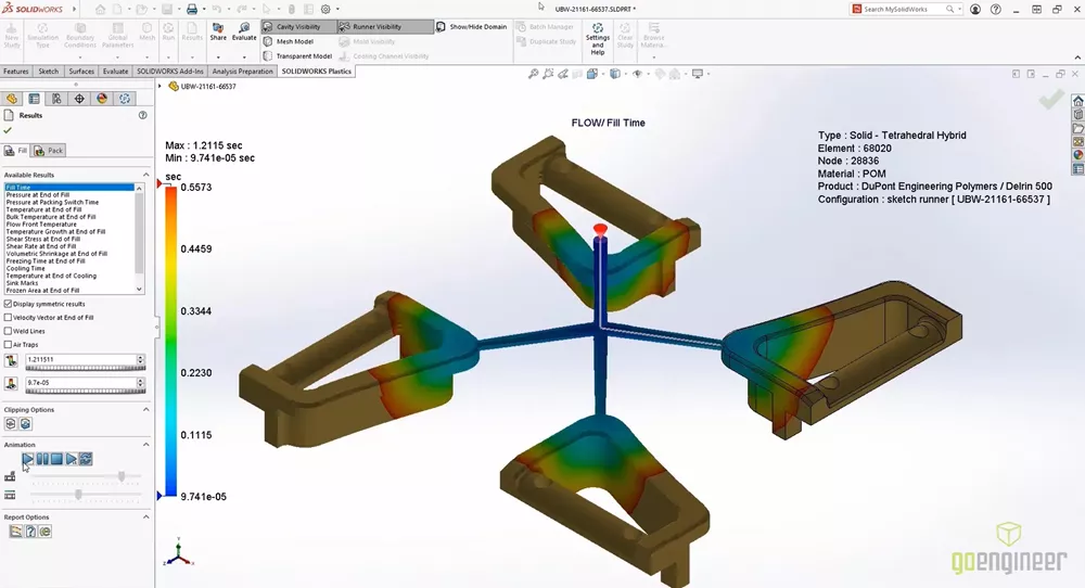
SOLIDWORKS Plastics 2022
SOLIDWORKS Plastics 2022 added more than 100 new materials and updated over 1,500 material properties.
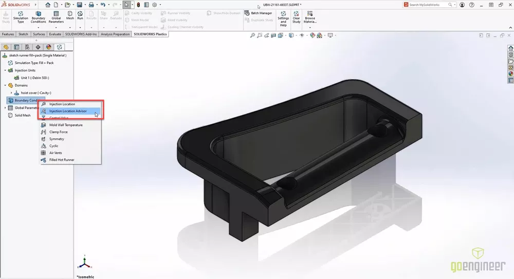
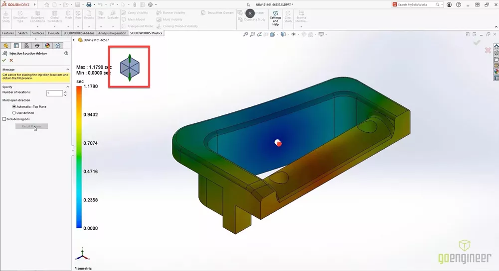
The new Injection Location Advisor optimizes and simplifies the selection of injection points and even calculates the best pull direction based on the geometry.
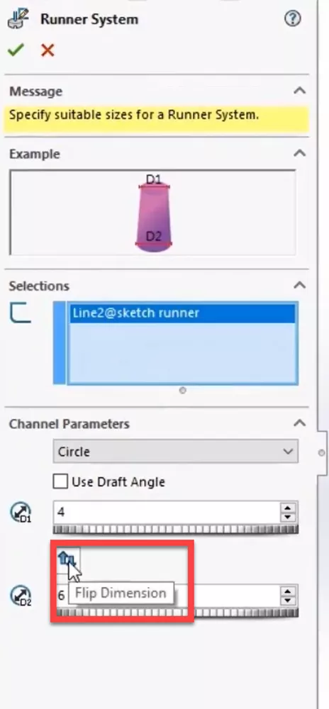
The Runner Tool has also been updated and simplified and the new Flip Dimension button makes runner system design even easier.
Users can use the Symmetry Boundary Condition to create family molds with symmetry in a snap, and the new Cyclic boundary condition allows for the creation of virtual cavities in a circular pattern.
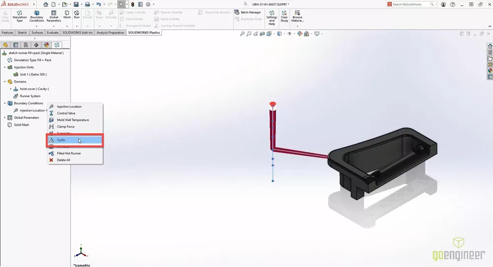
Users can even visualize all of their results in full symmetry as well.
![]() See these new features in further detail and more of what's new in SOLIDWORKS Plastics 2022 in this video.
See these new features in further detail and more of what's new in SOLIDWORKS Plastics 2022 in this video.
Enjoy seeing what’s new? Stay up to date by following us on social and subscribing.
More What's New SOLIDWORKS 2022
What's New SOLIDWORKS 2022: 3DEXPERIENCE
What's New SOLIDWORKS 2022: Graphics & User Experience
What's New SOLIDWORKS 2022: Routing, Structure Systems, Parts & Features
![]()
About GoEngineer
GoEngineer delivers software, technology, and expertise that enable companies to unlock design innovation and deliver better products faster. With more than 40 years of experience and tens of thousands of customers in high tech, medical, machine design, energy and other industries, GoEngineer provides best-in-class design solutions from SOLIDWORKS CAD, Stratasys 3D printing, Creaform & Artec 3D scanning, CAMWorks, PLM, and more
Get our wide array of technical resources delivered right to your inbox.
Unsubscribe at any time.