SOLIDWORKS Flow Simulation Parametric Study Tutorial
SOLIDWORKS Flow Simulation allows users to automate the change of flow and/or model parameters to investigate the influence of these changes on the flow behavior of the system. This type of automation can be done through the creation of a Parametric Study.
Flow Simulation Project
Setup
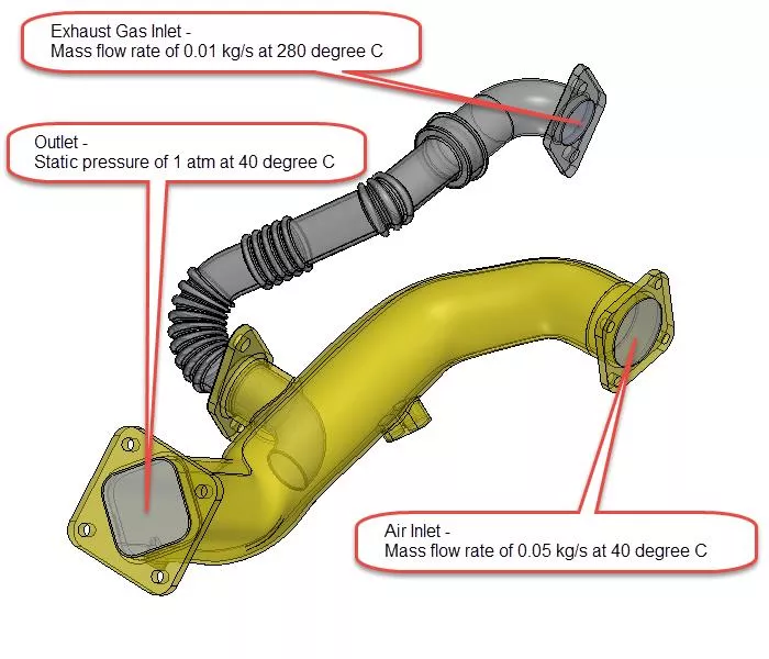
In this example, I set up a flow simulation analysis of an exhaust system. Exhaust gas enters the exhaust tube and mixes with air flowing through the main manifold tube. The goal of the analysis is to investigate the air/exhaust gas flow mixture at the outlet of the system.
Results
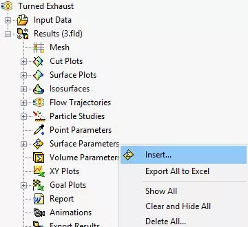
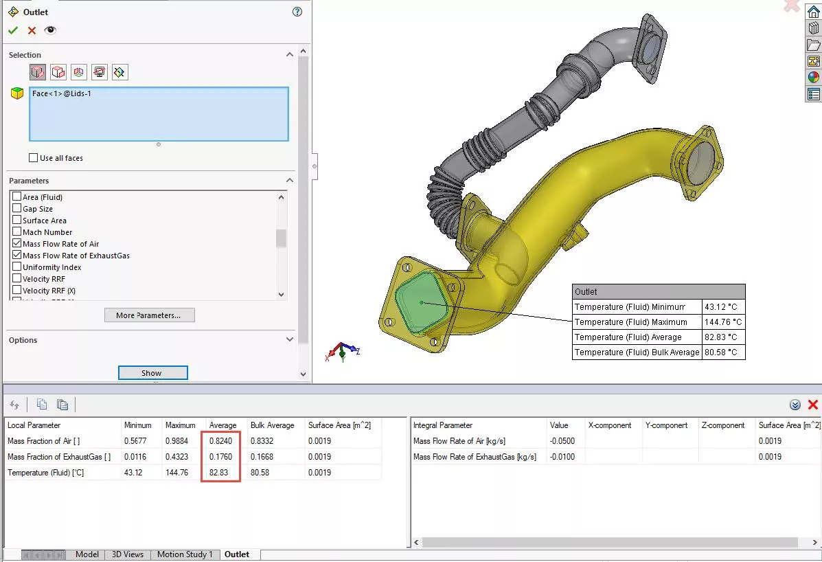
The Surface Parameter feature was used to output results at the outlet.
The average mass fraction of air and exhaust gas at the outlet is 0.824 and 0.176, respectively. The average temperature of the air/exhaust gas flow mixture at the outlet is 82.83 °C.
Parametric Study
To investigate changes in the outlet flow behavior based on different inlet exhaust gas mass flow rates, I can manually clone the project multiple times, update the inlet condition, and then rerun it. A better approach is to set up a Parametric Study to automate the inlet exhaust gas mass flow rate change and the rerunning of the flow simulation project.
Setup
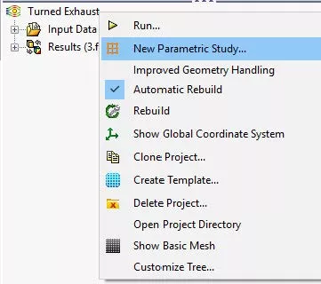
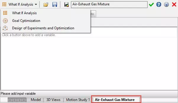
A Parametric Study can be created by right-clicking on the name of the project at the top of the Flow Simulation project tree and selecting New Parametric Study.
The Parametric Study dialogue shows up at the bottom of the SOLIDWORKS interface. A pull-down menu at the upper left-hand corner allows for the user to switch the Parametric Study type. In this example, a What If Analysis will be run which requires the definition of Input Variables.
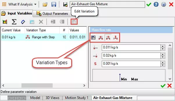
Input Variables
Input Variables can be specified as flow parameters, equations/global variables, model dimensions, and design table parameters. There is no limit to the number of input variables that can be defined. However, few inputs should be varied at once so that trends are understood correctly.
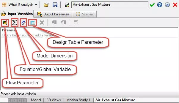
Flow parameters can be tied to several different inputs including General Settings entities, mesh settings (local and global), and Boundary Conditions. Equations/global variable inputs and design table parameters require an equation or design table to exist in the model. Also, any driving dimension can be tied to an input variable. For example, this can be a sketch, feature, or mate dimension.
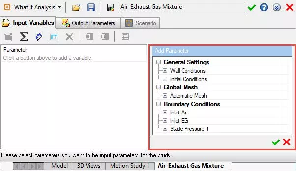
In this example, an input variable is tied to the mass flow rate of the inlet exhaust gas boundary condition.
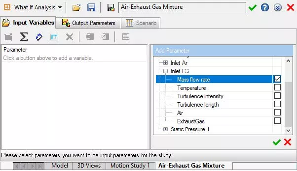
The variation type can be specified as discrete values or a step option can be defined to generate the inputs. In this example, 10 values have been defined using the Range with Step variation type.
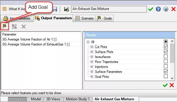
Output Parameters
Output parameters can be tied to project goals and result plots. They are used to display results in the parametric study dialogue and are not needed to run the study.
Scenario
The scenario tab displays the summary of the project and is where the Run option is located. Solver options can be modified, new projects can be created and additional manual design points can be added on this tab.
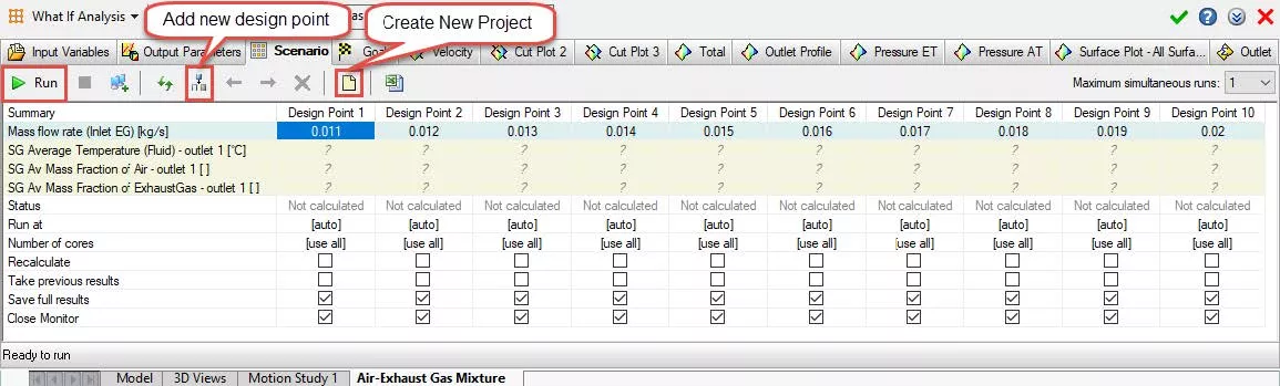
Results
Full results for every design point iteration are stored for the study. However, projects are not automatically created for each study. New projects can be manually created after the study has been run by accessing the scenario tab. Results are automatically linked to the new project. This allows for in-depth post-processing. Output parameters can be queried via the various tabs at the top of the dialogue.
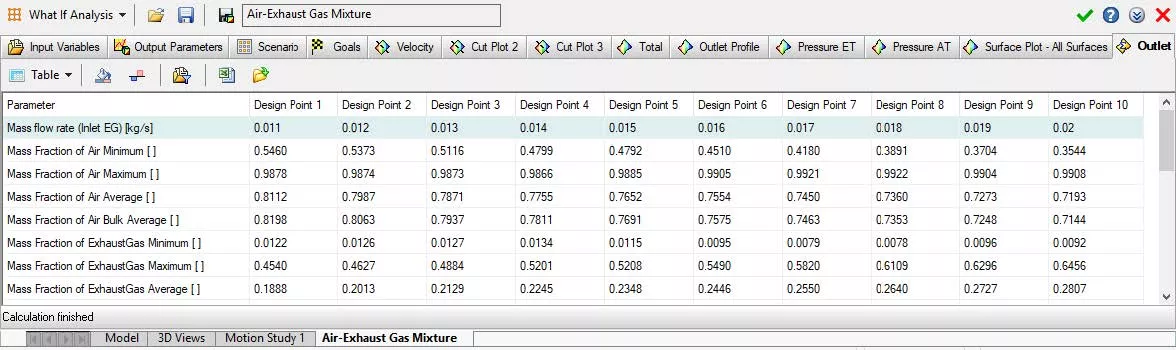
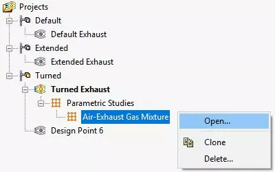
The parametric study is saved in the project tree and can be accessed at a later time.
More SOLIDWORKS Flow Simulation Tutorials
Customizing SOLIDWORKS Flow Simulation Feature Tree Categories
Tank Sloshing Using SOLIDWORKS Flow Simulation
5 Steps to Take Before Every SOLIDWORKS Flow Simulation Analysis
SOLIDWORKS Flow Simulation: Isolate Parts in a Temperature Solid Plot
![]()
About GoEngineer
GoEngineer delivers software, technology, and expertise that enable companies to unlock design innovation and deliver better products faster. With more than 40 years of experience and tens of thousands of customers in high tech, medical, machine design, energy and other industries, GoEngineer provides best-in-class design solutions from SOLIDWORKS CAD, Stratasys 3D printing, Creaform & Artec 3D scanning, CAMWorks, PLM, and more
Get our wide array of technical resources delivered right to your inbox.
Unsubscribe at any time.