CREAFORM VXINSPECT
create inspection reports using CAD or scan data
What is VXInspect Software?
VXinspect is an inspection software add-on module fully integrated into Creaform’s VXelements main software, which directly interfaces with all of Creaform’s hardware measuring devices. Scanner-only inspection is supported along with other devices such as scan and/or probing workflows. It allows companies to use their Creaform 3D scanners to their fullest potential by enabling them to create repeatable FIA (first article inspection) plans and reports for their Quality Control needs. The software is flexible, allowing the user to create reports using CAD or scan data as the nominal model (reference), or have no model reference and use a 2D drawing when creating the inspection plan.
Tools
CREAFORM VXINSPECT
Advanced Inspection tools for Creaform measuring devices.
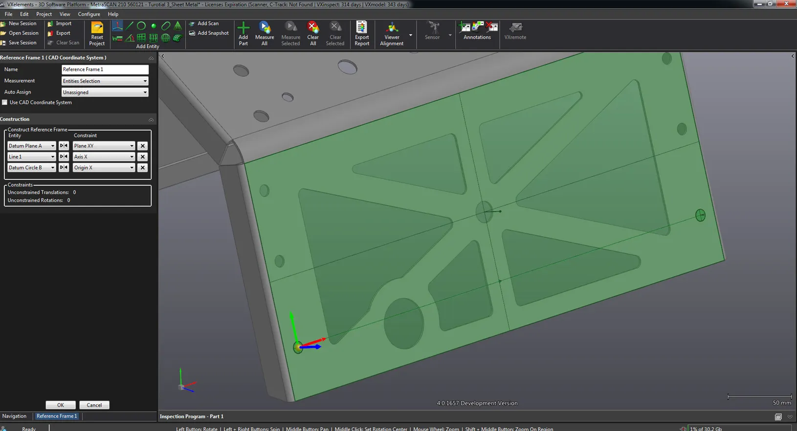
Data Alignment
VXinspect has various quick alignment routines, such as surface best-fit using measured scan data to a nominal CAD or mesh file, entity alignment using user created entities, and datum alignments can be performed with either scan or probe data.
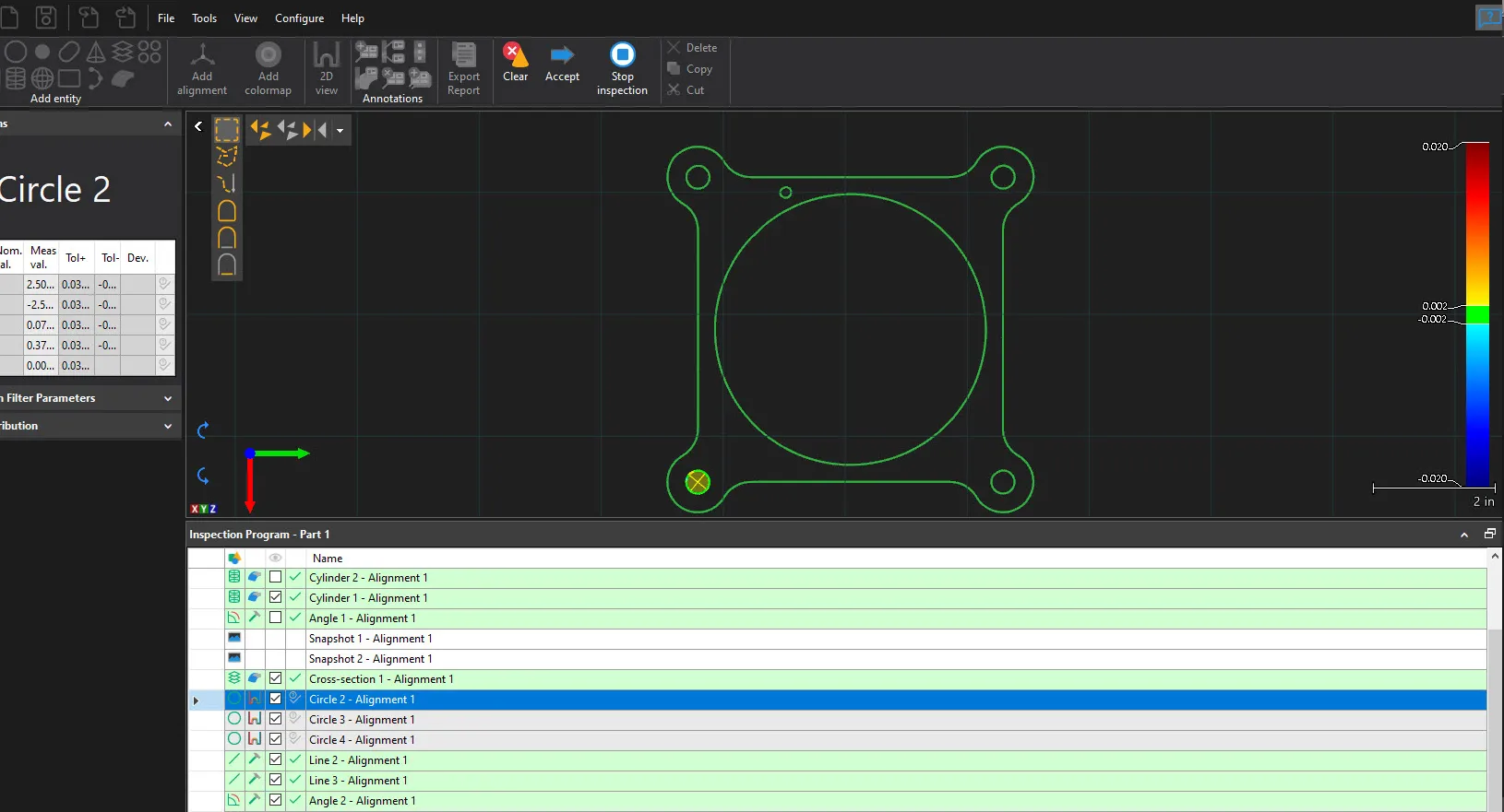
Cross Sections
Users can create various cross sections of the data to show deviations between the measured part and the nominal model. These are shown as colored whiskers that correlate to an editable colorbar showing the high and low areas of deviation. Discrete deviation points can be added by the user for better communication.
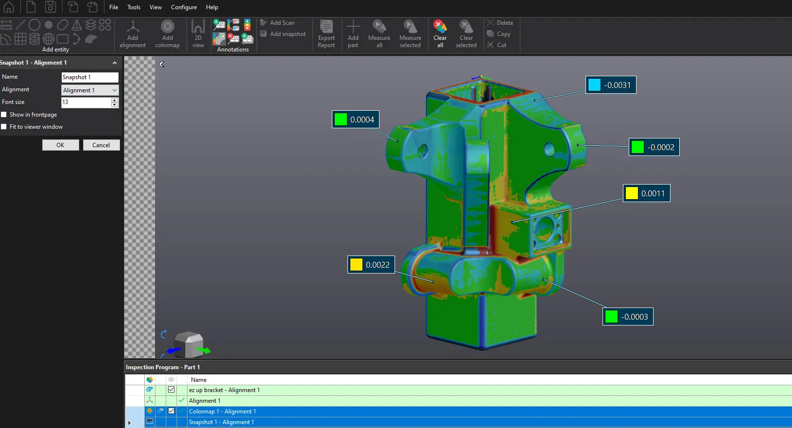
Snap Shots
Users can customize their reports by adding graphic snap shots of dimensions and deviation color maps shown in the 3D viewer. Various annotations can be added including entity callouts and colormap grid showing discrete deviation points on the data. Snap shots can be re-ordered in the inspection program and passed along to the report.
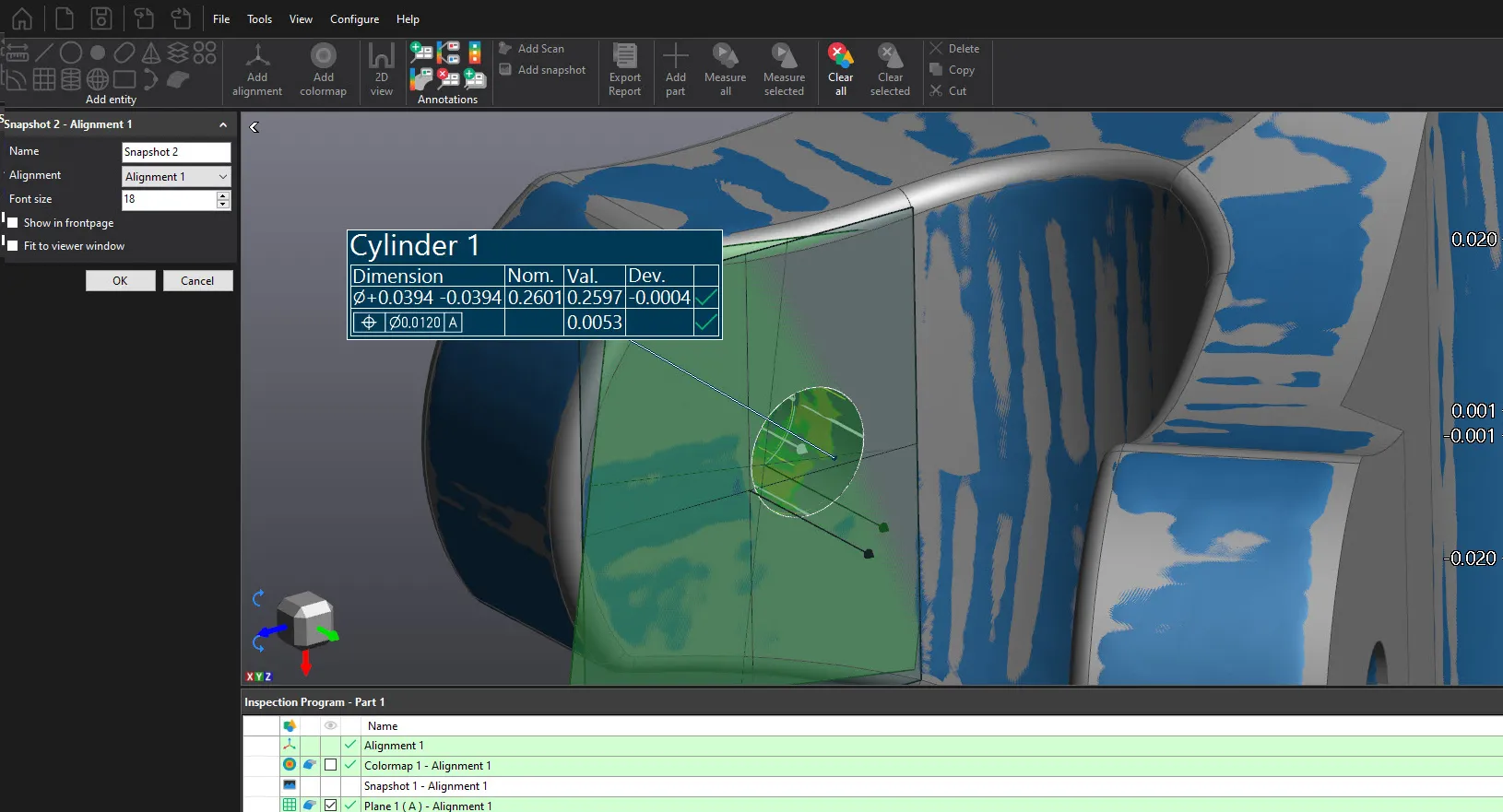
GD&T Support
Geometric Dimensioning and Tolerancing is supported in VXinspect if required. Straightness, Flatness, Circularity, Cylindricity, Line profile, Surface profile, Perpendicularity, Angularity Parallelism, True position, and Concentricity callouts can be added to various created entities and shown in the report.
Frequently Asked Questions
X INSPECT Features
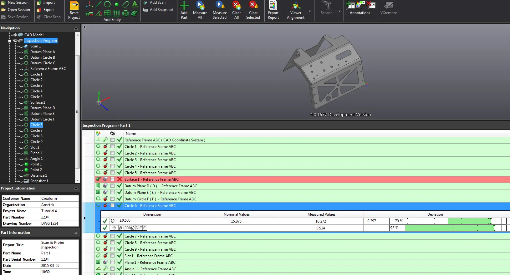
Repeatable Inspection Sequence
The user created inspection plan can be repeated if multiple parts of the same part exist, expediting the inspection process saving time and money. The plan is shown graphically as a list in the Inspection Program window, also showing how each entity is to be measured. Measured entities can be created by triangle (mesh) selection, hard probe contact, targets (optical probe), constructed, as well as other methods. These entities can be edited if necessary in the plan, and also re-measured and verified at any time during the inspection process.
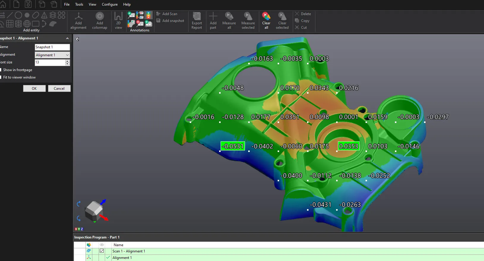
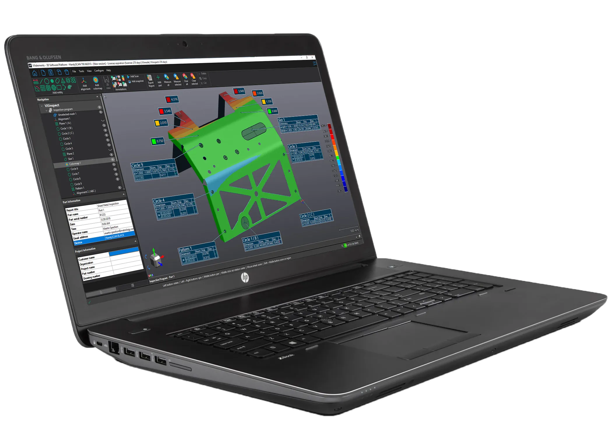
Colormaps
3D colormaps can be created and personalized with a click of a button showing the deviation between the entire mesh and nominal model, or on specific prismatic entities created. The associated colorbar can also be edited showing continuous or discrete colors, user-defined colors and the tolerance range. Various annotation types can be added and placed around the 3D viewer for clearer communication of deviation. A scalable color grid can be quickly added as well as user defined points placed around the colormap.
Additional Resources
Take Advantage of GoEngineer’s Extensive Knowledge Base and Resources

Find a Solution
Our robust Knowledge Base contains over 12,000 resources to help answer your product design questions. From basic CAD questions to in-depth guides and tutorials, find your solution here. Find a Solution

PROFESSIONAL TRAINING
Improve your skills with professional training and certifications in SOLIDWORKS, CAM, 3D Printing, and 3D Scanning offered four ways: self-paced, online, on-site, or in-classroom. Certified Training Courses

BLOG
#1 Technical Resource Worldwide - Right at your fingertips. Search or browse through hundreds of SOLIDWORKS tips & tricks, additive manufacturing product developments, announcements, how-to guides, and tutorials. Blog
YouTube Channel
Our YouTube channel hosts hundreds of educational tutorials, product demonstrations, recorded webinars, and best practices for all of our products and services. GoEngineer's YouTube Channel
ONLINE STORE
Order 3D printing materials and consumables, enroll in SOLIDWORKS training classes, and buy official GoEngineer gear directly from our online store. Online Store
WEBINARS
Our engineering webinars are hosted by some of the top experts in the industry. They are always recorded, always free, and always offer a live Q&A. WEBINARS
3D Printing Services
Need to 3D print a part? Our Additive Manufacturing experts will 3D print your part and deliver it to you using the latest technology on one of our professional FDM, PolyJet and SL 3D printers. 3D Printing Services