Using Sketched Contours to Create 3D Extrusions in DraftSight
In my last blog – Introduction to Basic 3D Shapes in DraftSight – I demonstrated the methods for creating the basic 3D shapes using DraftSight Premium or DraftSight Enterprise Plus. I want to continue that demonstration by showing you how to use sketched contours to create 3D extrusions.
To create a solid from a contour you will need to use the EXTRUDE Command.
From the DraftSight Help:
“The Extrude command creates solid primitives by extruding closed 2D entities such as PolyLines, Circles, Ellipses, and Regions.
Use the Extrude command to create 3D solids or 3D surfaces.”
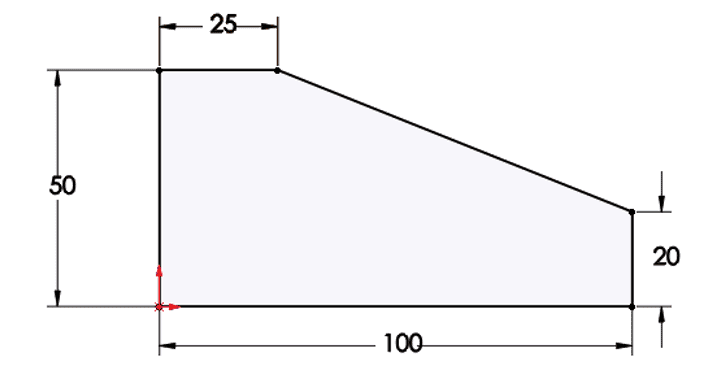
I will start with a simple shape from the SOLIDWORKS Essentials Training Exercises.
Then create the shape in DraftSight using the Polyline tool. By using the Polyline tool a closed contour of continuous lines will be created.
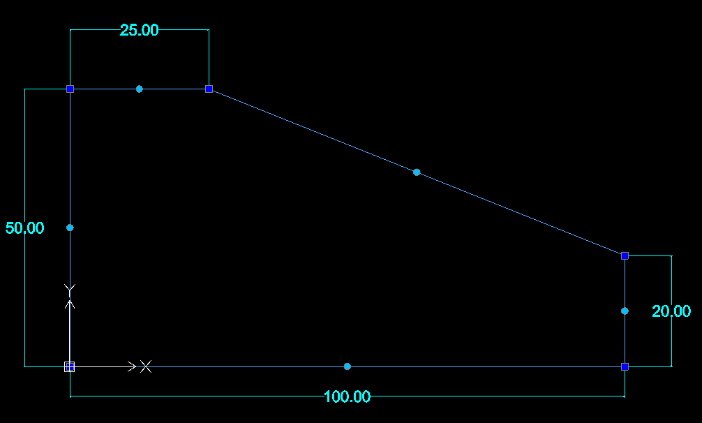
This is what the Polyline contour looks like when a single line is selected
If you draw the shape using the LINE tool. It will look like this when all of the lines are selected.
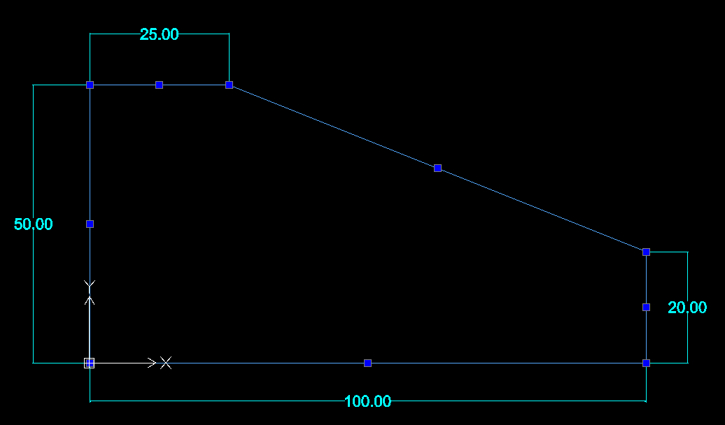
The Polyline sketch is a single region while the Line sketch is 5 separate entities. To use it for the EXTRUDE command you will need to convert the lines into a Polyline or into a 2D Region entity.
From the DraftSight Help:
The Region command transforms an entity that forms a closed shape into a 2D Region entity. You can use the command to combine all entities of any closed loop – such as closed PolyLines (including polygons and Rings), Circles, Ellipses, and closed Splines – into one entity.
After creating a Region, there is little visual difference on screen except when the original entity had a width, thickness, or LineWeight. This information is lost when you create a region from such entities.
A Region is a planar solid entity. If you set ShadeView mode to Flat, you will see that the Region is a surface, not simply a boundary contour.
If the source entities of the Region are hatched, the Hatch loses associativity to the boundary. You must apply the Hatch to the Region entity again.
You can also create Regions with the AreaBoundary command by setting the resulting entity type for boundaries to Region.
Another method would be to convert the lines to a continuous polyline using either the WELD or JOIN command.
From the DraftSight Help:
Use the Weld command to merge two entities into one. You can merge Lines, open PolyLines, Arcs, elliptical Arcs, or open Splines. You can also transform Arcs to Circles and elliptical Arcs to Ellipses.
Use these guidelines when welding entities:
- Lines must be aligned in one direction. You can join Lines that are co-linear, in which case the farthest end points remain and a new line connects them.
- Lines that are not co-linear, without space between them, are joined to a PolyLine.
- Arcs must share the same center point and radius. Arcs are joined counterclockwise beginning from the source entity.
- Elliptical Arcs must lie on the same Ellipse. Elliptical Arcs are joined counterclockwise beginning from the source entity.
- PolyLines can join Lines, Arcs, or PolyLines resulting in a single PolyLine. You can only merge entities that lie end-to-end to the source PolyLine and attached specified entities. The entities must lie on the same plane. Unlike joining Lines, Arcs, or elliptical Arcs, you cannot join entities with a space between them if the source entity is a PolyLine. Note that the EditPolyLine command also lets you join entities to existing PolyLines.
- Splines must have no gaps between them. The appearance of the Spline changes if the transition between the origin entities is not tangential.
Either command will prepare the sketch for the EXTRUDE command.
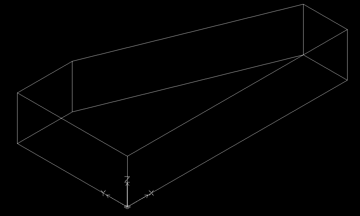
Change the view to SW Isometric.
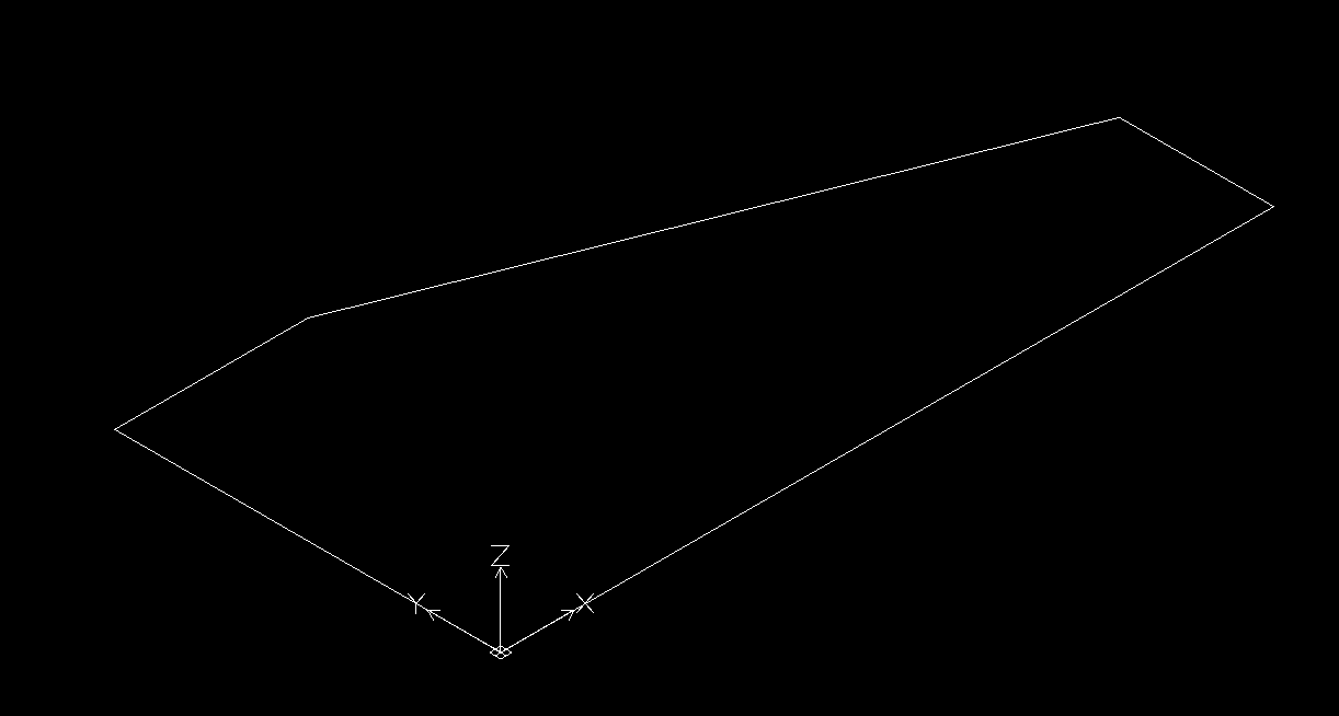
Type EXTRUDE in the command line. Set the height to 20 and the result should look like this:
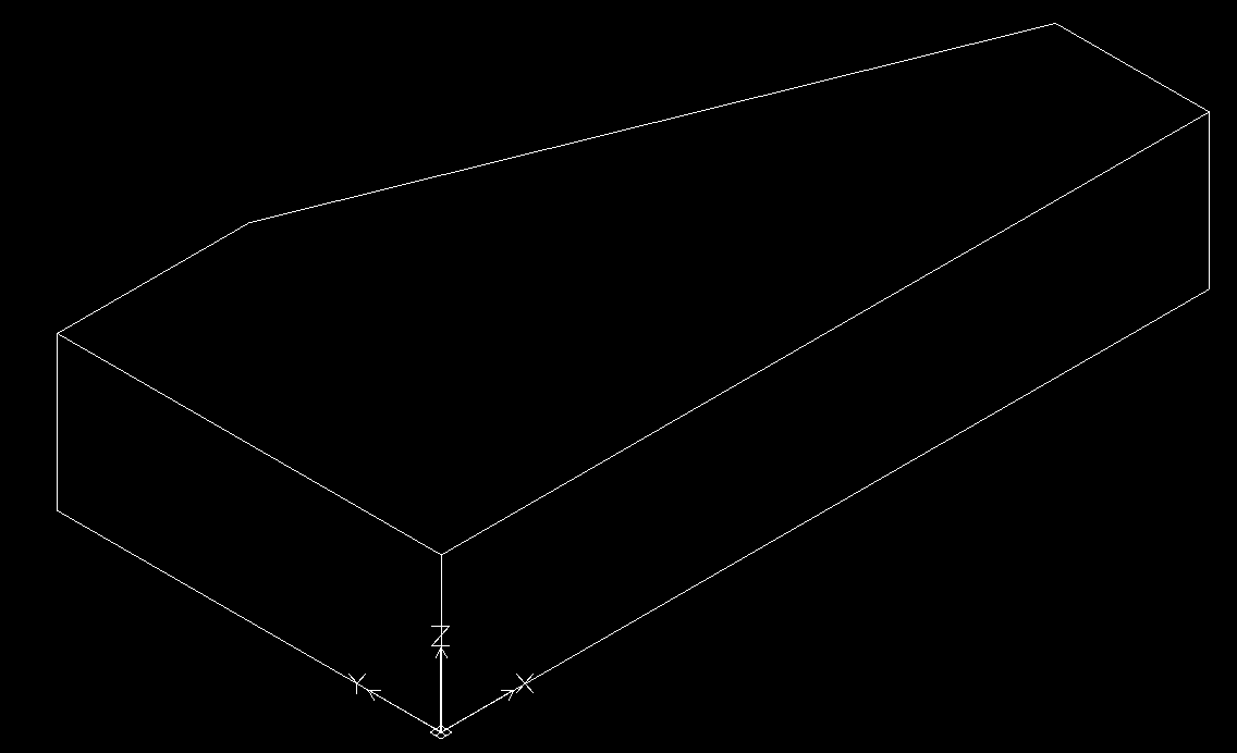
To change the appearance use the HIDE or Hideview command. This will hide the lines behind the view. like this:
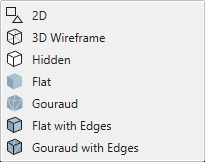
Or, you could use the shading commands :
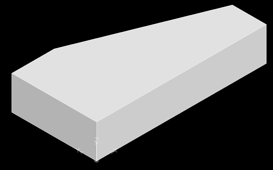
For example, using the Flat with Edges command will look like this:
I hope you enjoyed this demonstration of the EXTRUDE command to create 3D solids from closed contours.
Stay tuned for more DraftSight design and modeling blogs at CATI.com.
Also please visit our blog for our other blog articles pertaining to DraftSight:
DraftSight for the AutoCAD User – Laura Nickerson
Master Layers in DraftSight with Layer States Manager – Dennis Barnes
Collaborative Designer for DraftSight Enhancements – Todd Myers
DraftSight Electrical Symbol Library Free Download – Judy Marlo
Inserting Blocks in DraftSight is SO Easy. Read on to Learn How! – Judy Marlo
Using Image Tracer in DraftSight – Dennis Barnes
DraftSight Network License Timeout – Kris Dubuque
![]()
Dennis Barnes
Application Engineer
Computer Aided Technology