5 Essential Tool Sets for Geomagic Design X
Digital fabrication hardware plays a key role in enabling businesses to become more agile in their ability to create and modify designs. Alongside product development, there is a tremendous amount of consideration put into the engineering of tooling for manufacturing a component.
A challenge that many companies face is the recreation and extraction of features from an existing design that does not have any native CAD associated with it. Be it legacy files, old/outdated tooling, or simply designs that have not been released by a vendor — reverse engineering has become essential to bridge the gap.
3D scanning has become a popular mode of enabling reverse engineering. Artec 3D scanners make it possible to capture features with up to 50um accuracy with ease. Upon processing the scanned object, the user can export a mesh based file (STL, OBJ, PLY, VRML, etc.) However, for many engineers who are used to designing in solid-parametric modelings suites, these mesh based files present a challenge for a designer who wishes to make changes to the original geometry.
Enter Geomagic Design X, a purpose built reverse engineering software that allows engineers to convert triangle based mesh geometries into parametric based CAD with editable feature history. There are a ton of features that allow the user to convert designs and export as popular parametric file types such as .STEP, .IGES or native CAD files for SOLIDWORKS, NX, Creo, etc.
Here I have highlighted a few features found within the typical reverse engineering workflow that details the power of Geomagic Design X:
1. Regions
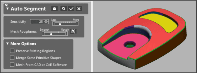
Using this automated tool, Design X (DX) segments and groups clusters of polygons together that can be used to create reference geometry. Based on the shape of the cluster, DX will determine if the region represents a plane, cylinder, sphere, torus, revolution, or freeform geometry. Throughout the workflow, these regions are used to recreate solid or surface based features. Regions are also used to create reference geometry, which allows a geometry to be aligned to the design space.
2. Reference Geometry
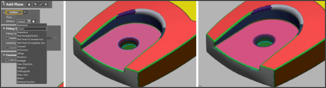
In order to recreate a design accurately, it is important to have the scanned geometry properly aligned and referenced in 3D space. Using the reference geometry tools it is possible to create planes, vectors, points, and coordinate systems. Simply select a related region and define what type of relation it would have (ex: extract, project, offset, tangent, mirror, etc.) Click finish and you are left with a reference feature that can be used to align the geometry to the 3D workspace or to create new design features.
3. Mesh Sketch
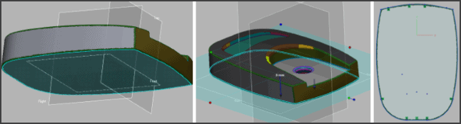
The mesh sketch tool provides an easy way to extract cross section profiles from a scanned geometry. These extracted cross sections become sketch profiles in which the user can dimension and select to model solid or surface features (extrusion, revolve, loft, sweep, etc.) Simply select the reference region or plane, an offset value, and direction and the cross section profile is automatically generated.
4. Auto Surface
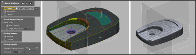
This is a button that makes your life easy. Simply select whether the geometry is mechanical or organic and DX will automatically wrap your object as a closed parametric surface. Click through the menu and manually edit your control points. When you are done you are left with a closed and knit set of parametric surfaces. This tool is great if the goal is to create simple surface offsets or quickly export a model as a .STP or .IGS.
5. Deviation Analysis
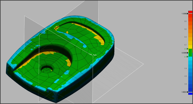
This tool will provide you with a heat map that displays the deviation value between your triangle based mesh and your parametric solid bodies. As a part is converted to a solid through the reverse engineering workflow, deviation analysis provides an easy graphical interface that details which features are most accurate.
The driving principles of many solid modelers such as SOLIDWORKS or Creo are transferrable to Design X. In fact, many people will find that redesigning a CAD file around an existing mesh will help them develop skills that allow them to become a better design engineer. Our goal is to find the best solution which fits a customer’s needs. We offer Design X as a standalone suite or as a plug-in for CAD suites such as SOLIDWORKS.
If you are spending precious time carrying out reverse engineering tasks, or are interested in evaluating 3D scans to parametric workflows reach out to us as 3DAE@fisherunitech.com. We are interested in providing tailor made hardware and software solutions which enhances your ability to adopt new 3D workflow and increase work efficiency.
Learn More
You can see an Artec 3D scanner demonstration in this video by one of Fisher Unitech’s scanning experts, Ben Hartwig.
Related Articles
Digitizing Real-World Objects With 3D Scanners
 About the Author
Danny Jackson Levy is a cross-functional design engineer, providing technical expertise for the integration of turnkey advanced manufacturing processes. He joined the Fisher Unitech team as a 3D Printing Application Engineer in August of 2015. Danny began his journey with 3D Printing technology in the startup world, and later worked with Duke University to develop college level 3D design and printing curricula. At Fisher Unitech Danny takes lead for healthcare and dental applications with the intent to evangelize additive manufacturing technology for personalized medicine. He hopes to one day 3D print a heart valve for his sister who was born with a ventricular septal defect. Follow his adventures on Instagram @Noosphere3D